How Return Loss Affects RF Filter Performance?
In radio frequency (RF) communications and high-frequency electronics applications, RF filters play a crucial role in ensuring signal integrity and system stability. Among these, "Return Loss" is a vital indicator of filter impedance matching quality, directly impacting signal transmission efficiency and overall system performance.
Temwell Group will guide you through an in-depth understanding of the definition, design implications, practical applications, and testing methods of Return Loss. We will also share how, through professional design and precise measurement, we help customers create RF filters and microwave components with optimal return loss and high stability, ensuring best matching performance at every signal frequency.
What is Return Loss of RF Filter?
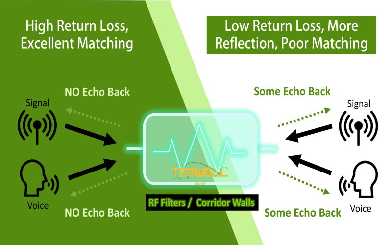
In radio frequency (RF) and microwave design, return loss (RL) is a crucial indicator of the input matching quality of a filter. It represents how much energy from the input signal is reflected back to the signal source due to impedance mismatch. Ideally, when the filter and system impedance (typically 50 Ω) are perfectly matched, almost all signal energy is transmitted to the output, with no reflection.
For example, if we compare sound to a signal: when you shout in a well-insulated room, the echo is very small, which means the return loss is high and the match is good; conversely, if there is a significant echo on a smooth wall, it means the return loss is low and there are many reflections.
Therefore, a higher return loss value (e.g., >20 dB) means less reflected energy, better matching, and more stable signal transmission efficiency in the system.
The Impact of Return Loss Values
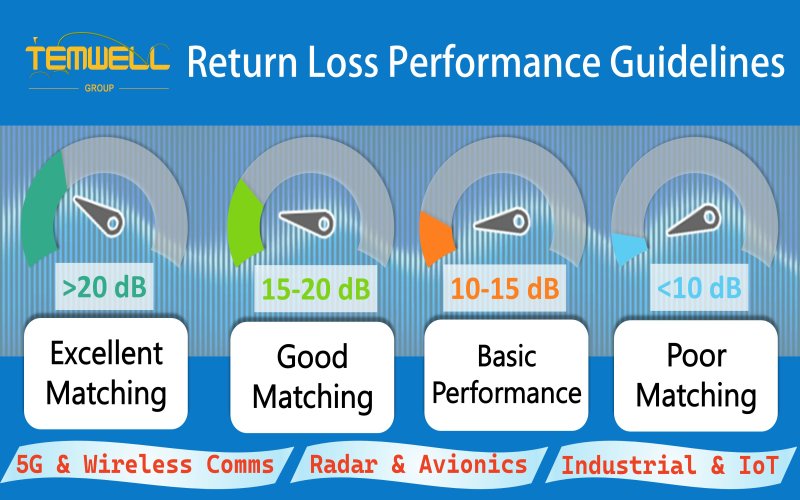
Return loss is expressed in decibels (dB) and is a positive indicator where higher is better. Generally speaking:
• Greater than 20 dB: Excellent matching, with reflected energy less than 1%.
• 15~20 dB: Good matching, suitable for most communication and industrial applications.
• 10~15 dB: Basic acceptable range, commonly found in cost-sensitive products.
• Less than 10 dB: Poor matching; redesign or impedance configuration is recommended.
The required return loss varies across different application areas depending on system sensitivity and performance specifications:
• Wireless communication and 5G modules: High-frequency signals are particularly sensitive to reflections. A return loss that is too low can cause signal distortion, gain instability, or interference problems. Therefore, a return loss of greater than 20 dB is typically required.
• Radar and avionics systems: A high return loss must be maintained across the entire operating frequency band to avoid positioning errors or signal interference caused by reflections.
• Industrial automation and IoT devices: Stable operation is typically achieved at 10–15 dB, but the impact of the operating environment (e.g., metal enclosure, humidity, and temperature variations) on matching must still be considered.
Engineers will balance parameters such as return loss, insertion loss, and bandwidth based on system design goals, frequency range, and application scenarios to achieve optimal overall performance.
How to Read Return Loss from plot?
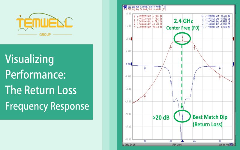
Return loss is typically presented as a "dB vs. frequency" graph, one of the most common graphs in filter performance reports.
• Horizontal axis (X-axis): Represents frequency (MHz or GHz).
• Vertical axis (Y-axis): Represents the Return Loss value (dB).
• Valley of the curve (Dip): Represents the frequency point with the lowest reflection loss, i.e., the optimal matching position.
For example, a Helical Bandpass Filter (Temwell model TTW3836B-2400M) with a center frequency of 2.4 GHz will typically have its deepest valley (e.g., -22 dB) on its Return Loss curve near that frequency, indicating minimal reflection and optimal energy transfer at this frequency.
In practical applications, engineers will simultaneously examine the following points:
1. Consistency of Return Loss within the passband: Confirming good matching across the entire passband.
2. Sideband or cutoff performance: Avoiding excessive reflections that cause interference.
3. Comparison of measured and simulated results: Ensuring that product measurements match design expectations.
A good Return Loss curve should be smooth and stable, without significant fluctuations or abnormal peaks.
Extensive design experience with Return Loss
In the practical development of RF filters, the control of return loss is not solely based on theoretical formulas, but rather on the results of multiple design cases and the summarization of results. The Temwell engineering team has accumulated the following key experiences over many years of RF product development. These practical details are the core foundation for a high-quality RF filter to consistently maintain excellent Return Loss performance.
1. Impact of Dielectric Materials and Conductor Quality:
The substrate dielectric of the filter (e.g., ceramic, dielectric, LTCC, or metal cavity) directly affects signal conduction and electromagnetic field distribution. Excessively high or unstable dielectric constants can lead to impedance shifts, causing a deterioration in return loss. Temwell uses highly stable dielectric materials to ensure stable matching performance at different frequencies and temperatures.
2. Structural Design and Electromagnetic Coupling Control:
Improperly spaced resonant cavities or coupling lines within the RF filter can easily cause reflections or unnecessary coupling interference. Temwell uses 3D electromagnetic simulation software (such as HFSS and ADS) to predict the impedance matching of each cavity in the early stages of design, reducing later adjustment time.
3. Connection Interfaces and Packaging Technology:
In high-frequency applications, even small differences in solder joints or connector pin lengths can alter the reflection path. Temwell employs high-precision assembly and coaxial packaging technology during manufacturing to minimize mechanical errors and electrical reflections.

Return Loss vs. VSWR: Understanding the Relationship
Return Loss and VSWR (Voltage Standing Wave Ratio) are two closely related metrics, both used to describe signal reflection and impedance matching quality.
• Return Loss: Expressed in dB, higher is better.
• VSWR: Expressed as a ratio, closer to 1:1 is better.
The two can be converted to each other using a formula. When the Return Loss is 20 dB, the VSWR is approximately 1.22:1; when the Return Loss reaches 30 dB, the VSWR is close to 1.06:1, indicating near-perfect matching.
In other words, Return Loss and VSWR are two ways of expressing the same phenomenon. Engineers can choose one for evaluation based on application habits or system specifications. We will discuss VSWR in later chapters.
Temwell Group Service - One-Stop Solution from Design to Mass Production
Temwell Group has been deeply involved in the RF and microwave filter field for over 30 years, possessing complete R&D, mass production, and testing capabilities to ensure that every product maintains excellent return loss performance and stable signal transmission quality in real-world applications.
Temwell's professional support includes:
* Complete product datasheets: covering key parameters such as return loss, insertion loss, bandwidth, and center frequency.
* High-precision simulation and test reports: multi-band verification using high-end network analyzers to ensure consistency between simulated and actual data.
* Reliability verification and environmental testing: temperature cycling, vibration, and long-term stability testing to ensure stable performance in harsh environments.
Product application areas:
* Communication equipment and antenna systems, radar modules, satellite and navigation devices, industrial and medical electronic equipment.
* Each filter is designed with high quality and precision manufacturing at its core, ensuring that return loss and overall performance meet high international standards.
Temwell's integrated services include:
* Technical evaluation and design advice: Providing optimal solutions based on frequency, power, and environmental conditions.
* Prototype design and rapid prototyping: Accelerating product development and market entry.
* Mass production and quality control: Strictly adhering to international RF component quality standards.
Temwell Group, with its extensive RF design experience, precise network analysis and measurement, and rigorous process control, ensures that every filter maintains excellent impedance matching and stable Return Loss performance. Upholding the professional spirit and quality commitment of "Made in Taiwan," we are dedicated to providing global customers with highly reliable RF and Microwave components, helping you build high-efficiency, low-reflection RF systems and achieve a more powerful wireless connectivity future.
If you are interested in Customized RF Filter Service, feel free to contact us and get free consultation services so that we can provide you with the best solution.
Subscribe to us on Facebook for the latest product news.


