How Customized service work in RF Filters?
Definition of Customized Filter Service:
Customized Filter Service is a professional process to design and manufacture a specific RF Filter according to the customer’s specific application requirements.
RF engineers will adjust the basic parameters of the filter according to customer requirements. Common parameters include center frequency, bandwidth, and rejection value. Engineers can also design for specific parameters, such as power, size, and package type. Our professional custom design team will select the most suitable filter technology (such as helical filter, cavity filter, DR filter, microstrip or SAW filter) based on the requirements of the overall parameter list. Through comprehensive simulation program calculations, coupled with the design team's years of design experience, we can ensure that the designed solution can fully achieve the target performance. After production is completed, professional instruments are used to measure and ensure that the performance accurately meets the required targets and meets the strict development requirements of base stations, radars, satellites and communication systems.
Difference from standard products:
Custom filter services provide product solutions tailored to the needs of specific applications. Standard products are products with fixed parameters, developed by suppliers based on experience. While standard products are more readily available, their fixed specifications often force users to design filters that accommodate these characteristics, impacting the performance of the final product. For example, if the standard product only has 450 MHz and 20 MHz bandwidths, and the system requires a narrowband, high-suppression design of 455 MHz and 8 MHz, the product design will not achieve the desired design goals. Through our customized filter services, we can adjust bandwidth parameters to ensure the optimally matched filter performance is incorporated into the design.

Customized Filter service includes as below.
1. Flexible RF Filter category
The core of customized filter service is "Selecting the most appropriate technical solution based on the customer's parameter requirements." Based on the customer's provided specifications, such as center frequency, bandwidth, insertion loss, rejection, power, and size limitations, we analyze and compare four mainstream filter technologies—Cavity, Helical, SAW, and DR—to recommend the design solution that best balances performance and cost.
Unlike standard products that utilize a single technology, customized services are not restricted to fixed architectures but instead offer the flexibility to utilize a variety of filtering principles. For example, Cavity filters can be used for high-power and low-loss applications; Helical filters can be used for medium-frequency narrowband applications; DR filters can be considered for high-temperature stability requirements; and SAW filters are suitable for high-frequency miniaturized modules. This open design approach ensures that each product achieves the optimal balance between performance, size, and reliability, resulting in truly customized and high-performance filter solutions.
2 Basic values of filters can be specified arbitrarily (FC / BW / IL / RL / Rejection)
The core of customized filter service is to allow customers to freely indicate the five main parameters of RF filter: center frequency (FC), bandwidth (BW), insertion loss (IL), return loss (RL), and stopband rejection (Rejection). These five values are the foundation of RF filter performance and crucial to overall circuit matching and system efficiency.
During the design process, engineers simultaneously consider the interplay between these five metrics. For example, narrower bandwidths improve rejection, but insertion loss may also increase. By analyzing the primary and secondary metrics defined by the customer, engineers can perform multi-level parameter pairing and trade-offs to identify the optimal combination. This design approach frees filters from standard specifications and allows them to be tailored to system requirements, balancing performance, stability, and practicality.

3. specify the power and size value
Customized filter services can be designed not only on frequency and bandwidth, but also on the RF filter parameters that often need to be modified: Power and Size, which can be customized according to customer needs. For example, base stations and radar systems must withstand high power inputs ranging from tens to hundreds of watts, while communications devices or modules require specialized dimensions to optimize internal circuit board design space.
A. Power Design:
Based on system output power and heat dissipation requirements, our customized service adjusts the filter structure and materials to ensure stable frequency response and low insertion loss even at high power input. For example, communication base stations, radar, or power amplifier systems require filters designed to withstand power ranging from 10W to over 200W while retaining sufficient safety margin. Common design power ranges include 100W, 500W, and 1kW to over 5kW, all of which can be customized.
B. Size Design:
Different communication devices or modules often require specific dimensions to optimize the internal circuit board design space. Customized Filter Service can redesign the cavity or resonant structure to meet specific length, width, and height requirements, achieving miniaturization and light weighting while maintaining the required filtering characteristics and reliability. This flexible design allows the filter to seamlessly integrate into various system architectures.
Customization services provide these two designs supports, allowing customers to more comprehensively obtain the most ideal and balanced filter solution between performance and integration.
4. Request for special parameters (ripple, group delay, and impedance)
In addition to freely setting basic center frequency, bandwidth, rejection value, power, and size, customized filter service also allows you to set specific performance specifications such as passband ripple, group delay, and impedance to meet application requirements.
These parameters are particularly critical for high-precision communications, radar measurement, and broadband transmission systems. Engineers can control the ripple amplitude within the passband to ensure signal amplitude consistency according to customer requirements, and adjust group delay flatness to reduce phase distortion and time delay variation, thereby improving system synchronization accuracy. Furthermore, if the system utilizes non-standard impedances (such as a 75 Ω matching structure), optimized matching design can be performed for specific impedance interfaces. Through precise adjustment of these high-order parameters, customized filters achieve an ideal balance between signal integrity, transmission stability, and system compatibility, meeting the stringent requirements of professional-grade RF applications.

Question from Customized Filter Service
1. How to calculate the expense?
When applying custom filter services, one of the most common questions engineers would ask is "how is the expense calculated?" Because custom service require re-adjustment and customization based on actual frequency range, bandwidth, insertion loss, power, and size requirements, the cost vary depending on the technology type and manufacturing complexity. The following is a cost overview and pricing rules for four major filter types:
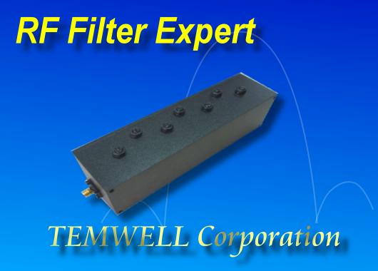
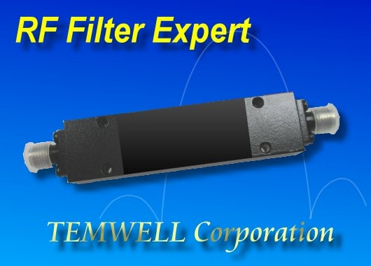
a. Helical Filters
This solution is in the economical-price range. Helical filter has a compact structure and high adjustability, and is suitable for mid-frequency band and narrowband applications. Cost depends primarily on the resonator order and tuning accuracy. Samples require a minimum order quantity of 10 units, and the total cost typically ranges from US$300 to US$800. The price will decrease with volume production.
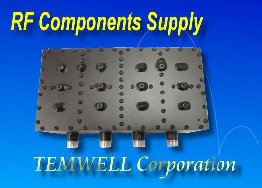
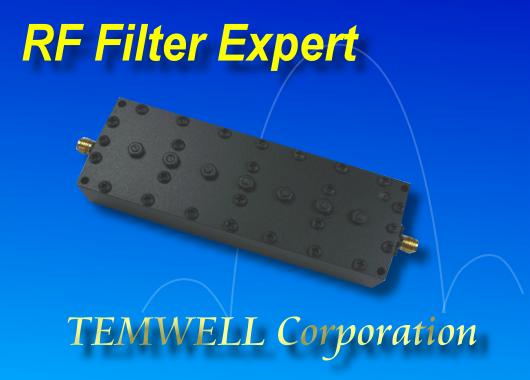
b. Cavity filters
These are the preferred choice for high-power and low-loss applications, featuring complex structures and high-precision manufacturing. Due to the complex materials and assembly process, the unit price is relatively high. Sample quantities of 1-5 pieces are acceptable, and the cost typically ranges from US$300 to US$2,000. The more difficult to achieve the specifications, the higher the development cost.
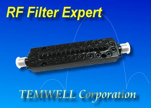
c. DR (Dielectric Resonance) Filters
These filters offer high Q and stable temperature characteristics, with a cost somewhere between Helical and Cavity. Pricing varies depending on the frequency and resonator size. Samples have a minimum order quantity of 10, and the cost typically ranges from US$700 to US$1,000. The price will decrease with volume after mass production.
d. SAW Filters
Using a custom SAW chip development process can meet the smallest possible miniaturization requirements. However, due to the need for a mask during customization, initial process costs are very high, typically ranging from US$50,000 to US$100,000. However, once mass production reaches thousands of units, the unit price can drop rapidly to US$0.5-1, making it suitable for projects with high potential demand.

2. How long Customized Filter service will take ?
One of the most common questions when requesting a custom filter service is, "How long does the development time take?" The actual timeframe varies depending on the filter you select. Below are estimated development times for four major filter types.
A. Helical Filters:
With a mature structure and rapid tuning capabilities, the filter allows for quick selection from a database. Solution evaluation can be completed in approximately three days. From design to prototype in approximately two weeks, this is the fastest development solution for mid frequency band and narrowband applications.
B. Cavity Filter:
A simulation evaluation will be conducted initially, and a recommended solution will be completed within 7 days. However, due to the metal processing and high-precision assembly involved in actual production, standard production of newly developed products can take 6-8 weeks, or even longer, to ensure the perfect implementation of customized product solutions.
C.DR (Dielectric Resonance) Filters:
Initial simulations and evaluations are conducted, and a design proposal can be completed within 7 days. Actual production involves powder mixing and sintering to create a customized ceramic resonator. Performance characteristics are repeatedly adjusted, and the typical production of a newly developed product takes 5-6 weeks.
Similarly, initial simulation and evaluations are conducted, and a design proposal can be completed within 7 days. Later stages of production involve wafer fabrication. Because there are no pre-defined mask designs, fabrication must begin from scratch. After sample completion, field testing, matching, and wafer adjustments are required to achieve the desired parameters. Development time is estimated to be approximately 15-20 weeks. However, once completed, mass production can be accelerated, enabling us to meet demand for 100,000-500,000 units in a short period of time.
3. Simulation proposal V.S. Real sample?
During the custom filter development process, many engineers often wonder, "Can the performance evaluated in simulations be fully realized in actual products?"
In reality, there has indeed slight differences between simulation results and measured values. These discrepancies are mainly due to practical factors such as manufacturing tolerances, material properties, welding structures, and test fixtures.
While modern electromagnetic simulation software (such as HFSS and CST) can accurately predict frequency response and insertion loss, in actual production, conductor surface roughness, dielectric constant errors, and even screw tightening torque can cause frequency offsets or changes in rejection.
However, if developed and manufactured by an experienced custom filter design company, through rigorous simulation verification, structural optimization, and actual measurement and adjustment, the achievement rate of simulated and actual performance can usually be significantly close to 100%.
To narrow this gap, the professional design team includes adjustable parameters (such as screw pitch and tuning screw position) during the simulation phase. Based on long-term development and design experience, various possibilities are taken into consideration in the evaluation plan. Fine-tuning is also performed during the actual measurement phase to ensure that the final results are almost completely consistent with the expected parameters of the simulation solution, ensuring that the product achieves optimal performance and reliability.
Therefore, a highly qualified and experienced custom development team is crucial. This team not only proactively identifies potential sources of error but also provides precise corrections during sample tuning and mass production, ensuring consistently reproducible design performance across each batch, truly embodying the value of professional filter development.

How to start customized filter service?
Custom filter services offer a complete development process, from requirements analysis to actual manufacturing, ensuring product performance perfectly meets system design requirements. Unlike passive selection of standard products, custom designs can be tailored to specific conditions such as frequency, bandwidth, insertion loss, rejection, size, and power, ensuring the filter achieves optimal performance within the specified environment. The entire process is typically led by a professional design team, encompassing four phases: specification confirmation, simulation analysis, sample production, and field testing. This ensures that design results closely align with actual performance. The following are the five key steps in a typical project opening.
1. Specify Required Development Parameters
First, customers must provide basic requirements, such as center frequency (Fc), bandwidth (BW), insertion loss (IL), stopband rejection (Rejection), power, size, and application environment. These parameters form the foundation of the design and can be provided through a requirements form, technical discussions, or specification documents. If the customer has a clear understanding of the desired parameter values, they can directly provide the data, and the design team will use this data for simulation and development. Clear requirements can expedite design evaluation and improve development efficiency.
2. Determine Primary and Secondary Parameters
After understanding the basic requirements, engineers will help customers determine design priorities. Primary parameters such as center frequency, bandwidth, and rejection are considered core objectives, while secondary parameters such as size and return loss are used to balance overall performance. Because these parameters interact with each other—for example, changes in bandwidth affect insertion loss and rejection—it's important to clarify which metric is the primary objective and which is adjustable. By clearly setting priorities, the design team can derive the most appropriate design direction among various technical solutions, balancing performance and feasibility.

3. Software Simulation
After confirming the design direction, engineers will use electromagnetic simulation software (such as HFSS or CST) to create a model and analyze the filter's frequency response, insertion loss, and group delay. The simulation process adjusts the data based on the ranking of primary and secondary parameters, selecting the optimal solution that meets the primary objectives from multiple structural models. Simulations can predict actual performance, verify feasibility, and help customers understand the trade-offs between different design approaches, making subsequent implementation more accurate and efficient.
4. Detailed Discussion and Adjustment
After the simulation results are released, both parties will conduct detailed discussions on performance curves, structural dimensions, and power configuration. If any discrepancies or new requirements arise, engineers will fine-tune the design parameters and structure to bring the simulation results closer to actual manufacturable conditions. Relying on an experienced design team is crucial at this stage. They can draw on past development experience to identify design feasibility, significantly increasing the success rate of the final implementation. This step is crucial to ensuring that the specifications can be met.
5. Prototype Production
After design confirmation, the prototype production phase begins. This process includes machining, assembly, and testing, with a test report and S2P file provided upon completion. Our experienced production team utilizes practical techniques to fine-tune and refine the machining and assembly process, effectively correcting tolerance errors and frequency deviations, significantly improving product quality and stability. Once the prototype passes verification, we move on to the mass production design or functional integration phase, leading to official deployment.

Temwell Customized Filter Service
Temwell is a worldwide professional filter manufacturer specializing in the RF and microwave fields for over 28 years, providing high-quality filtering solutions for industries such as communications, radar, aerospace, test equipment, and wireless modules. As frequency accuracy, size constraints, and system integration requirements become increasingly stringent across various applications, standard products are no longer sufficient to meet diverse design needs. Leveraging its extensive design experience and comprehensive production system, Temwell offers one-stop customized filter services, from specification analysis and simulation design to prototyping and mass production.
The company boasts cross-domain technical integration capabilities, enabling us to tailor filters to meet customer-specified system requirements, including frequency, bandwidth, insertion loss, rejection, power, and size. The following describes Temwell's service advantages in five key areas: experience, proven track record, development capabilities, technical team, and customer support.
A. 28 Years of Professional Experience
Temwell has over 28 years of experience in filter design and manufacturing, specializing in the development of filtering technologies for the RF and microwave fields. From early analog design to today's high-precision electromagnetic simulation analysis, Temwell has accumulated extensive experience across frequency bands and applications, enabling it to provide precise solutions tailored to the needs of diverse industries (communications, aerospace, radar, and measurement equipment). This deep foundation in design and manufacturing enables Temwell to consistently deliver high-performance, highly reliable products in the field of customized filters.
B. Extensive Achievements and Mass Production Capabilities
So far, Temwell has successfully developed and mass-produced over 10,000 filter products of varying specifications, covering a wide range of frequency bands from 45 MHz to 60 GHz. The company possesses a comprehensive mass production system and high-yield manufacturing processes, with annual shipments exceeding 100,000 units. This achievement demonstrates that Temwell is not only capable of completing single-project development, but also possesses long-term, stable supply and continuous production optimization capabilities, ensuring that each custom filter meets industry standards for performance and consistency.

3. Up to 98% Solution Implementation Rate
Temwell customized design solutions offer exceptional feasibility, with an average development success rate exceeding 98% over the years. Leveraging a rigorous requirements analysis process, electromagnetic simulation, and field-tested calibration techniques, the design team accurately predicts and achieves customer-specified center frequency, bandwidth, insertion loss, and rejection targets. This high implementation rate means Temwell not only designs theoretical models but also ensures that actual product performance is virtually identical to simulation results, significantly improving the efficiency and reliability of customer development projects.
4. Four Major Filter Technology Design Teams
Temwell boasts a robust filter design team covering four major technology areas: Cavity, Helical, DR (Dielectric Resonance), and SAW (Surface Acoustic Wave). Each filter technology is developed and tested by dedicated engineers to ensure the optimal architecture and materials for each application. From high-power, low-loss Cavity designs to the highly stable and miniaturized SAW technology, Temwell flexibly combines these technologies to create customized filter solutions with optimal performance and the most stable structure for our customers.
5. Comprehensive Customer Protection Policy
Temwell fully understands the importance and confidentiality of customer development projects and has therefore established a comprehensive protection system. NDAs (Non-Disclosure Agreements) are signed during the initial development phase to safeguard customer technical data and design parameters. After product completion, Temwell provides comprehensive design data and production line protection measures to prevent leakage and unauthorized copying. This rigorous product protection policy allows customers to develop projects with peace of mind, ensuring the highest level of protection for their proprietary technology and market competitiveness.
Whether you are a student, RF engineer or radio enthusiast, if you are interested in Customized RF Filter Service, feel free to contact us and get free consultation services so that we can provide you with the best solution.
Subscribe to us on Facebook for the latest product news.