What is Insertion Loss of RF Filter

Definition of Insertion Loss
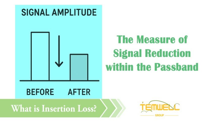
RF filters are indispensable key components in radio frequency circuits, responsible for allowing signals of a specified frequency to pass smoothly while blocking other unwanted interference. Insertion loss (IL) measures how much signal energy is lost as it passes through the filter's passband.
Imagine you are speaking, and the filter is like a door. Ideally, the sound (signal) can pass through completely, but if the gap is narrow or there is sound-absorbing material, the sound will be quieter. This "degree of quietness" is the insertion loss.
In other words, insertion loss reflects how much energy is absorbed or reflected when the filter allows the correct signal to pass through, and it is an important indicator for judging the quality and passband efficiency of the filter.
How to Evaluate If an RF Filter's Insertion Loss Value Is "Good" or "Bad"?
Insertion loss is usually expressed as a negative decibel (dB), such as -1.0 dB, but when discussing "loss", engineers are used to saying its absolute value directly, such as 1.0 dB.
The principle for judging performance is simple: the lower the insertion loss, the better.Good value: Approximately 0.5 dB or less, indicating minimal signal energy loss and high throughput. Poor value: More than 3 dB, representing a significant reduction in the amount of signal energy transmitted.
When designing wireless communication systems, such as mobile phones or base stations, we want filters to have the lowest possible loss while allowing useful signals to pass through. This is because:
1. It affects power loss: Any dB of loss directly reduces the strength of the transmitted or received signal. Typically, 3 dB of loss means half the signal power!
2. It affects the noise figure: High Insertion loss increases the system's noise figure (NF), thus affecting the receiver's sensitivity.
Therefore, reducing insertion loss is one of the core objectives in RF filter design to ensure high performance and high sensitivity.
Common Ways Manufacturers Specify Insertion Loss on Datasheets
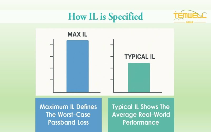
Format 1: Single Maximum Value (Maximum IL)
Specifications often state "maximum insertion loss must not exceed X dB", for example: IL ≤ 1.5 dB (within the 800–900 MHz passband). This means that the filter's signal loss will not exceed 1.5 dB across the entire passband. This is the most common and practical representation in design and verification.
Format 2: Typical Value
Some datasheets provide a "typical insertion loss," such as 1.0 dB, representing the average or common loss under normal operating conditions.
Note: Typical values are for reference only. Engineers should still use the maximum value (Maximum IL) as the reliable basis for design.
How to find the insertion loss value from the "S21 curve" of the filter?
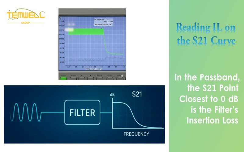
Filter performance is typically measured using a network analyzer (N/A) and presented as an S-parameter curve. Insertion loss corresponds to the measured value of the S21 curve in the "passband".
*What S21 Represents and How It Relates to Insertion Loss?
It represents the signal transmission coefficient from the filter input (Port 1) to the output (Port 2), measured in dB.
*Graph Explanation:
The horizontal axis represents frequency, and the vertical axis represents the dB value. Within the passband, the S21 curve is typically located in a high region close to 0 dB; However, within the stopband, the curve drops rapidly to low values such as -40 dB and -60 dB, indicating that the signal is effectively suppressed.
Interpretation steps:
1. Confirm the frequency band range.
2. Observe the highest point of the S21 curve within this region.
3. The value at this highest point (e.g., -1.2 dB) is the insertion loss, indicating that the signal loses approximately 1.2 dB of energy after passing through the filter.
Insertion Loss (IL) vs. Attenuation value: Key Differences and Design Trade-Offs
In radio frequency (RF) filters, insertion loss (IL) and attenuation are closely related. Although both are expressed in dB, their functions and meanings are completely opposite, they are located in different places, and they influence each other, both being key parameters determining filter performance.
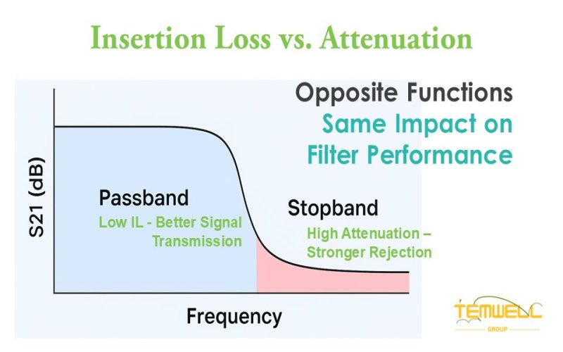
Insertion loss (IL) primarily describes the energy loss of the filter within the passband, representing the reduction in signal strength when the useful signal passes through. Ideally, a lower IL is better (closer to 0 dB represents almost lossless signal transmission).
In contrast, attenuation measures how well a filter suppresses unwanted signals in the stopband. A higher value indicates a more effective filter at blocking interference. For example, -60 dB attenuation performs better than -30 dB.
However, these two are not independent: increasing the attenuation capability in the stopband often increases the insertion loss in the passband. This "inverse relationship" is one of the most challenging trade-offs in filter design. An excellent design requires achieving the best balance between low insertion loss and high suppression to ensure that the system's sensitivity and stability meet the requirements at the same time.
How to Select a Reliable RF Filter with Optimized Insertion Loss?
Temwell is committed to providing precise and reliable RF filters and microwave components. All products come with complete and clear technical specifications, detailing key parameters such as center frequency, bandwidth, insertion loss, and return loss. We use high-precision network analyzers (N/A) for measurement and verification to ensure that every product exhibits stable and consistent performance in real-world applications.
Temwell's design philosophy is to pursue the lowest signal loss and the highest reliability, so that users can obtain the best performance in any communication environment. Whether you are a student researching wireless communications, an engineer conducting RF experiments, or a manufacturer developing high-stability modules, Temwell's filter products can be a reliable long-term partner.
If you are interested in Customized RF Filter Service, feel free to contact us and get free consultation services so that we can provide you with the best solution.
Subscribe to us on Facebook for the latest product news.


