

Design of Cavity Bandstop Filters with Sharp Attenuation Skirts for Interference Mitigation
In an increasingly congested spectral environment, the bandstop filter (BSF) plays a role complementary to that of the bandpass filter: it removes a single known interferer with surgical precision while leaving the rest of the spectrum untouched. This paper presents a systematic study of cavity bandstop filters with sharp attenuation skirts. It first establishes the quantitative definitions of skirt, shape factor and selectivity; it then analyses the four principal routes to introducing finite-frequency transmission zeros (TZs) — cross-coupling bridges, multi-network coupling, high unloaded-Q cavities and coupling-matrix synthesis; and it examines the composite attenuation obtained by cascading a cavity BSF with lowpass or highpass filters, together with the inter-stage matching issues this raises. Targeting f0 = 885 MHz with a 820–950 MHz stopband, a six-pole Chebyshev bandstop prototype (0.05 dB passband ripple, FBW = 0.393) yields BW3dB = 310 MHz, BW60dB = 128 MHz and a shape factor of 2.43, consistent with the published specifications of the TEMWELL Standard Cavity Bandstop Filter line (rejection ≥ 60 dB, insertion loss ≤ 2.0 dB, VSWR ≤ 2.0). Public-safety band interference mitigation is used as the application case study, illustrating how the ≥ 45 dB adjacent-band suppression requirement is met in practice. Finally, for deep-rejection (> 60 dB) measurement, the paper quantifies how insufficient vector network analyser dynamic range systematically under-reports rejection depth, and proposes five countermeasures — IF bandwidth reduction, averaging, source power, segmented sweep and noise-floor extension — before concluding with selection and customisation guidelines.
1. Introduction: Bandstop Filters in Interference Mitigation
1.1 Background
A bandstop filter passes most frequencies while strongly attenuating a specific band; it is the complement of the bandpass filter. When the stopband is narrow and the cavity Q high, it is generally called a notch filter. In RF and microwave systems it is used to suppress known narrowband interferers, adjacent-channel noise or self-oscillation without disturbing the rest of the spectrum. [1][2][3]
Typical scenarios include duplex interference suppression in base stations, image-noise removal in radar, adjacent-station protection in broadcasting, and spectrum cleanup in multi-band coexistence environments. In public-safety communications, a bidirectional amplifier (BDA) must pass the target public-safety band while suppressing adjacent commercial cellular bands — such as 800 SMR or LTE Band 14 — by more than 45 dB to prevent uplink/downlink cross-interference. Because a bandstop filter attenuates only a specific narrow band and barely affects passband insertion loss, it is a more precise and lower-loss solution than a broadband attenuator. [4][5][6]
The cavity structure uses air as its transmission medium and offers a rugged build, stable and reliable performance, high unloaded Q, good heat dissipation and distant higher-order spurious passbands. It is therefore particularly well suited to narrowband, deep-rejection bandstop responses and is one of the most common practical implementations. [5][6][25]
1.2 Motivation and Objectives
As spectrum grows scarcer, isolation requirements between adjacent systems keep rising while the available guard band keeps shrinking. This imposes two simultaneous and mutually constraining demands on the bandstop filter: rejection greater than 60 dB within the stopband, and recovery to below 2 dB of passband insertion loss over a very short frequency interval on either side. Classical Chebyshev and Butterworth prototypes place transmission zeros only at infinite frequency and cannot produce a sufficiently steep rise near the stopband edges.
The objectives of this study are:
- (1)to establish quantitative definitions of skirt, shape factor and selectivity as a common language for specification;
- (2)to review systematically the four principal techniques for introducing finite-frequency transmission zeros with a limited cavity count;
- (3)to analyse the composite attenuation and inter-stage matching issues arising when a cavity bandstop filter is cascaded with lowpass or highpass filters;
- (4)to map the findings onto TEMWELL's production specifications using public-safety interference mitigation as a case study; and
- (5)to clarify the instrument dynamic-range conditions required for deep-rejection measurement, so that specification verification is not distorted.
2. Defining the Attenuation Skirt: Shape Factor and Selectivity
2.1 Basic Response of a Cavity Bandstop Filter
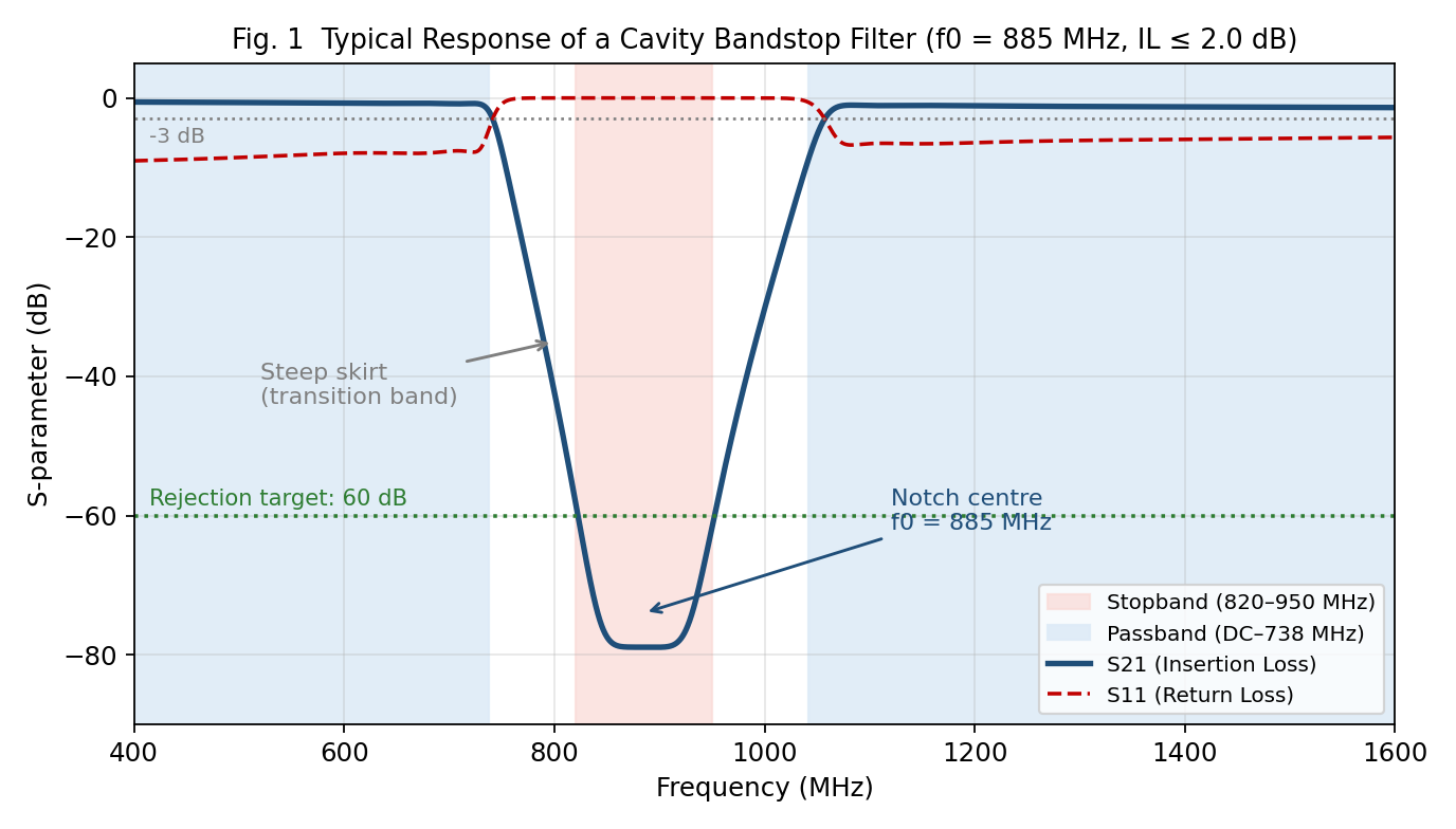
A cavity bandstop filter can be viewed as one or more high-Q resonant cavities shunted across a transmission line. At the resonant (notch centre) frequency, energy entering the cavity is reflected back out of phase with the original signal, creating a virtual short of near-zero impedance across the line; most of the applied energy is reflected back toward the source by the resulting impedance mismatch, with only a small fraction absorbed and dissipated in the cavity. Away from the centre frequency the cavity presents a high impedance and provides almost no attenuation. [25]
Fig. 1 shows the typical S-parameter response of an f0 = 885 MHz cavity bandstop filter. Three essential characteristics are visible: S11 approaching 0 dB within the stopband (near-total reflection), passband insertion loss held below 2 dB, and the rapidly recovering skirts on either side of the stopband. This reflective — rather than absorptive — mechanism is a key premise for high-power system design.
2.2 Skirt, Shape Factor and Selectivity
The skirt describes how steeply the response transitions from the passband (low attenuation) to the stopband (high attenuation); the faster the transition, the better the selectivity. Selectivity reflects how much of the filter's total bandwidth is consumed by the transition band — the narrower that band, the more guard band is saved and the higher the spectral efficiency. [7][8]
The core metric for skirt steepness is the shape factor, defined as the ratio of bandwidths measured at two different attenuation levels:
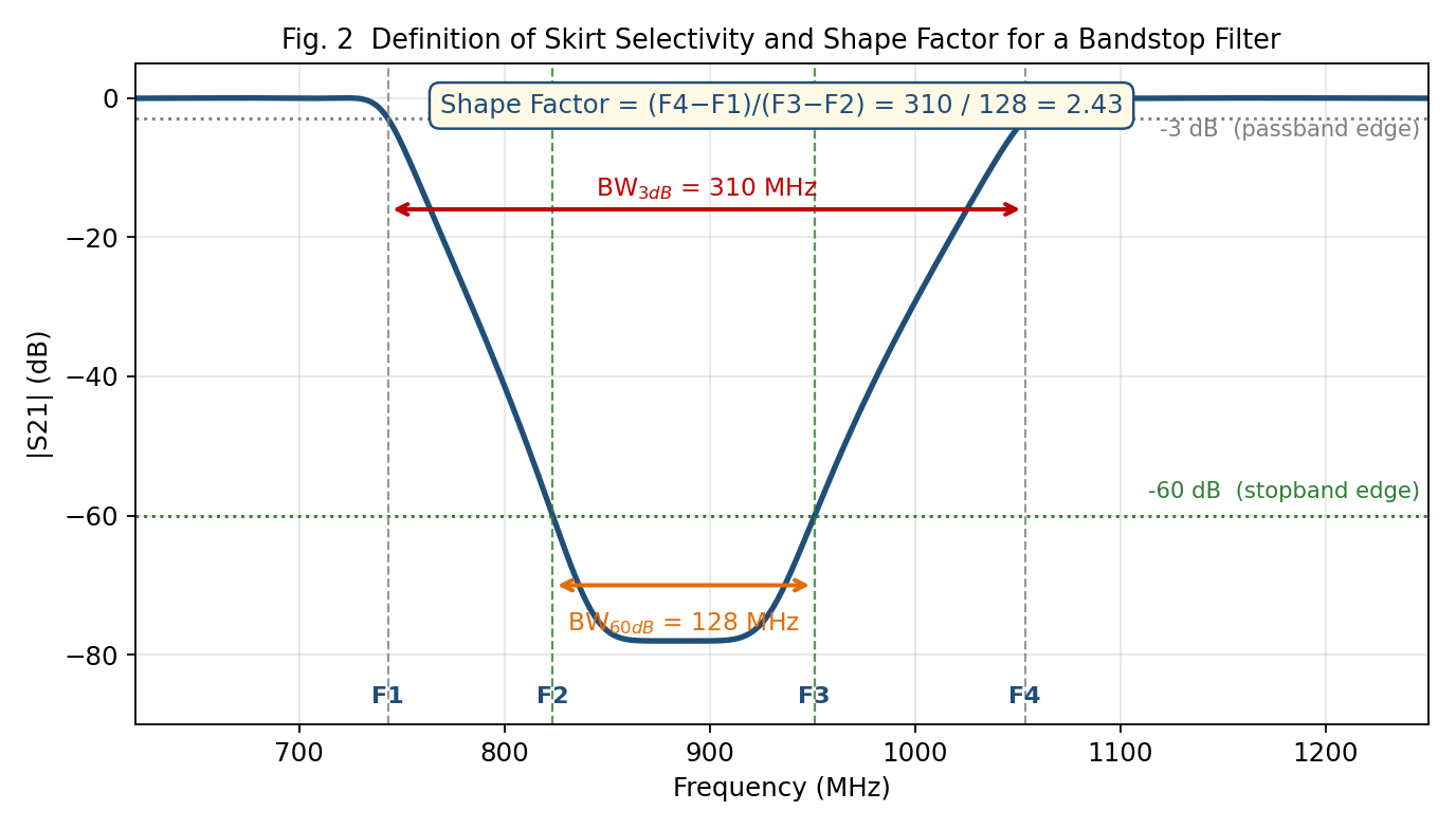
For a bandpass filter, F2 and F3 are the passband (3 dB) edge frequencies and F1 and F4 the stopband (60 dB) edges. In a bandstop filter the roles are reversed: the 3 dB crossings lie outside and the 60 dB crossings inside, so the shape factor is computed as the 3 dB bandwidth divided by the 60 dB bandwidth. In either case, a value closer to unity indicates a steeper skirt and better selectivity. [9][10][7]
Fig. 2 marks the four key crossings for the design target of this paper. With a six-pole Chebyshev bandstop prototype (0.05 dB passband ripple, FBW = 0.393), BW3dB = 310 MHz and BW60dB = 128 MHz give a shape factor of 2.43. The resulting 60 dB rejection range matches the 820–950 MHz specification of the TEMWELL 885 MHz standard model, and the passband edges (745 / 1052 MHz) are close to the published 738 / 1042 MHz.
The influence of pole number N on the shape factor follows directly from the Chebyshev prototype. Table 1 lists the theoretical shape-factor limits and design implications for 0.05 dB passband ripple.
| Pole number N | Theoretical shape factor | Skirt behaviour | Design implication |
|---|---|---|---|
| 2 | ≈ 30.1 | Single-cavity notch, attenuation recovers fast | Only for very narrow band, single interferer |
| 4 | ≈ 4.60 | Usable skirt but wide transition band | Entry configuration for general adjacent-band suppression |
| 6 | ≈ 2.38 | Sharp; the configuration adopted here | Balance point between deep stopband and narrow transition |
| 7 | ≈ 1.98 | Very sharp | Passband IL and tuning difficulty both rise |
| 8 | ≈ 1.74 | Approaching a rectangular response | Volume, cost and tuning time increase substantially |
Table 1 shows that the shape factor improves rapidly with pole number but with diminishing returns, while every added pole raises passband insertion loss and tuning complexity. When a sharper skirt is required with a limited cavity count, introducing finite-frequency transmission zeros is therefore usually more efficient than simply adding poles — the subject of Section 3.
3. Design Techniques: Introducing Transmission Zeros
3.1 Operating Principle of Transmission Zeros
The core technique for achieving a sharp skirt is to introduce finite-frequency transmission zeros (TZs) into the transfer function, driving S21 toward zero (infinite attenuation) at chosen frequencies. Classical Chebyshev and Butterworth prototypes generate transmission zeros only at infinite frequency; adding cross-coupling or multiple coupling paths creates zeros at finite frequencies, markedly improving both skirt steepness and stopband depth. [11][12][13]
3.2 Cross-coupling Bridges
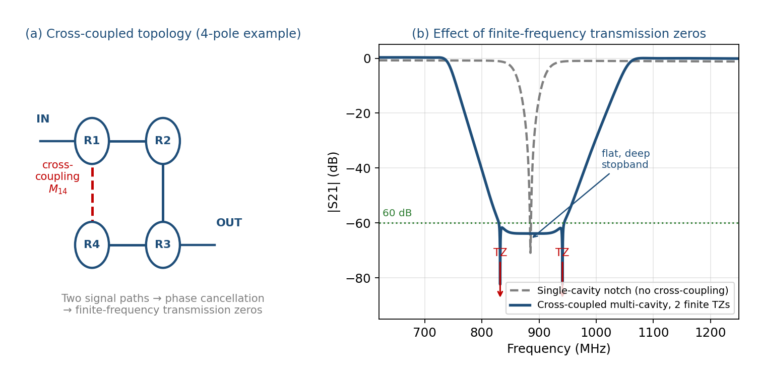
An additional coupling path between non-adjacent resonators creates two or more propagation routes through the filter. Where the two paths are of comparable magnitude and opposite phase, cancellation occurs and a transmission zero is formed at that frequency. This raises both notch depth and skirt slope without increasing the cavity count. [12]
Fig. 3(a) illustrates the common M14 cross-coupled topology using a four-pole structure; Fig. 3(b) compares a single-cavity notch with a cross-coupled multi-cavity design. The latter forms two additional transmission zeros within the stopband, expanding the region of ≥ 60 dB rejection from a few tens of megahertz into a flat, deep stopband while markedly steepening both skirts.
3.3 Multi-network Coupling
Mutual suppression between different coupling networks places one transmission zero either side of the stopband centre, producing a symmetric dual-zero notch response. This is particularly effective where a wide and deep stopband is required. A reported wideband bandstop filter with three transmission zeros measured deep rejection at 1.39 GHz (46 dB), 2.14 GHz (55 dB) and 2.89 GHz (53 dB), achieving 87.3% fractional bandwidth at the 20 dB rejection level — confirming that multi-zero techniques can deliver both deep rejection and a wide stopband. [14][15]
3.4 Narrowband High Unloaded-Q Cavity Design
Raising the unloaded Q of each cavity moves the transmission poles and zeros closer to the real axis, making the stopband attenuation curve both steeper and deeper. In practice, Q is raised principally by increasing the physical cavity size (mechanical Q). Larger cavities improve selectivity without significantly increasing insertion loss, but this is a design change rather than a field adjustment, and in most cases it does not alter the depth limit of the selectivity. [11][25]
3.5 Coupling-Matrix Synthesis
Suitable for narrowband designs with fractional bandwidth under 10%. Designing the coupling coefficients within the coupling matrix gives direct control over transmission-zero placement and stopband selectivity; physical dimensions are then extracted by eigenmode simulation. A published narrowband high-rejection cavity filter followed exactly this flow: coupling-matrix synthesis software fixed the order, zero configuration and topology, yielding the coupling bandwidth and quality factor, which were then verified by HFSS full-wave modelling. Measurements achieved 50 dB rejection at 2515 MHz, in-band insertion loss of about 5 dB and return loss better than 20 dB. [13][26]
| Technique | Principal effect | Best suited to | Limitation |
|---|---|---|---|
| Cross-coupling bridge | Raises notch depth and skirt slope together | Limited cavity count with sharp skirt requirement | Coupling value is tuning-sensitive |
| Multi-network coupling | One zero either side; wide, flat, deep stopband | Wide stopband with deep rejection | High structural and tuning complexity |
| High unloaded-Q cavity | Poles and zeros nearer the real axis; steeper and deeper | Narrow stopband with low IL | Increased volume and cost |
| Coupling-matrix synthesis | Direct control of zero placement and selectivity | Narrowband designs with FBW ≤ 10% | Accuracy degrades for wideband designs |
4. Composite Attenuation: Cascading with Lowpass and Highpass Filters
An ideal bandstop filter can be regarded as a lowpass and a highpass filter combined in parallel: the lowpass section passes signals below the stopband centre, the highpass section passes those above it, and the intersection forms the stopband. In practical cavity designs, however, a single bandstop filter attenuates only near the notch centre and its selectivity vanishes rapidly further out, making it unsuitable on its own where both a notch and broadband suppression are required. [1][5][25]
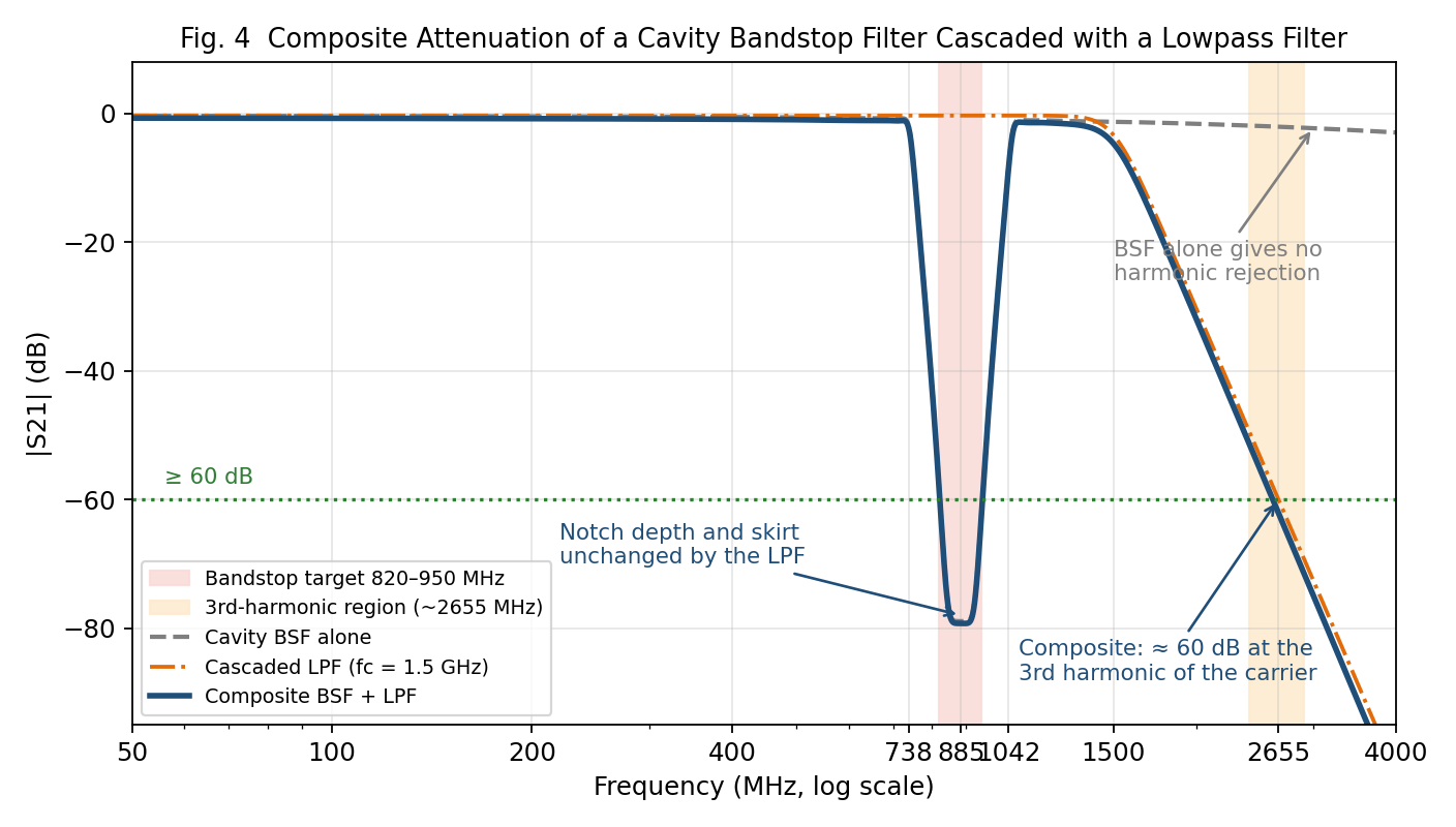
The usual remedy is to cascade the cavity bandstop filter with a lowpass (LPF) or highpass (HPF) filter, adding attenuation in a chosen direction outside the stopband. Fig. 4 uses a cascaded 1.5 GHz lowpass as the example: the bandstop filter alone offers virtually no rejection at the third harmonic of the carrier (≈ 2655 MHz), whereas the composite response reaches about 60 dB there — while the depth and skirts of the 885 MHz notch remain entirely unaffected.
The TEMWELL Standard Cavity Bandstop Filter line illustrates this: its specifications define several passband intervals at once (for example DC to one frequency, plus a higher frequency up to several GHz) while delivering more than 60 dB of rejection in the central stopband. This wide-dual-passband, narrow-deep-stopband structure is precisely the embodiment of combined lowpass / bandstop / highpass design. Table 3 summarises the typical specifications, showing that passband range and rejection depth follow a consistent design principle as centre frequency rises. [16][5]
| Centre freq. (MHz) | Passband range | Stopband rejection | Insertion loss | VSWR |
|---|---|---|---|---|
| 760 | DC~630 MHz & 902~2800 MHz | ≥ 60 dB @ 700~820 MHz | ≤ 2.0 dB | ≤ 2.0 |
| 885 | DC~738 MHz & 1042~3500 MHz | ≥ 60 dB @ 820~950 MHz | ≤ 2.0 dB | ≤ 2.0 |
| 1025 | DC~855 MHz & 1210~4000 MHz | ≥ 60 dB @ 950~1100 MHz | ≤ 2.0 dB | ≤ 2.0 |
| 1190 | DC~990 MHz & 1408~4500 MHz | ≥ 60 dB @ 1100~1280 MHz | ≤ 2.0 dB | ≤ 2.0 |
Note that the composite attenuation is not a simple linear sum: inter-stage impedance matching and return-loss interaction must be taken into account. Within its stopband the bandstop filter approximates a short circuit with a reflection coefficient near unity; if the input impedance of the following stage is not properly handled over that band, reflected energy oscillates between stages, degrading passband insertion loss or introducing unwanted ripple. The whole multi-stage structure should therefore be jointly optimised in electromagnetic simulation rather than designed stage by stage and simply cascaded. [17][18]
5. TEMWELL Case Study: Bandstop Design for Public-Safety Band Interference
Public-safety communication systems — the dedicated 800 MHz and 700 MHz police, fire and EMS networks — typically sit immediately adjacent to commercial cellular bands in urban areas, making them vulnerable to intermodulation interference and blocking from high-power neighbours. The standard remedy is a bandstop filter at the front end of the bidirectional amplifier (BDA), suppressing the adjacent interfering band (such as 800 SMR or LTE Band 14) by more than 45 dB while preserving low insertion loss within the public-safety band itself. [4]
Three specification characteristics define this scenario. First, the guard band is extremely narrow — interferer and protected band are often only a few megahertz apart, demanding a shape factor near or below 2. Second, rejection depth is high — 45 dB is the floor and practical specifications are usually written at 60 dB. Third, passband loss is critical — every additional decibel of insertion loss at the BDA front end directly erodes receive sensitivity. The simultaneous presence of all three is precisely why the high-Q cavity bandstop filter has no ready substitute.
The TEMWELL Standard Cavity Bandstop Filter series is designed for exactly this need, offering several narrowband high-rejection models across 700–1600 MHz with rejection generally exceeding 60 dB and passband insertion loss held within 2.0 dB — directly applicable to interference isolation at public-safety base-station front ends. Such designs typically combine a multi-cavity coupled structure with transmission-zero techniques, pulling deep rejection out rapidly at the stopband edges while maintaining low passband loss, meeting the demanding narrow-guard-band, high-rejection requirement of public-safety applications. [5][4]
A second, often overlooked application is transmitter sideband-noise reduction. Besides the carrier at its assigned frequency (typically 50 W / +47 dBm to 100 W / +50 dBm), a transmitter also radiates harmonics and broadband noise outside its allocated bandwidth; regulations require such emissions to be attenuated by 43 + 10 log(P) dB. The notch filter's advantage is that it can attenuate only a few hundred kilohertz from the carrier, whereas a bandpass filter often needs more than 1 MHz of guard band — sometimes several cascaded stages — for the same result. Its limitation is equally clear: the notch is effective over only a very narrow band, so it is unsuitable for sites with co-located transmitters or multiple same-band receivers. [25]
6. Measurement Considerations: Dynamic Range for Deep Rejection (> 60 dB)
Once stopband rejection reaches 60 dB or more, the dynamic range of the measurement system itself becomes the limiting factor on result credibility. A vector network analyser's dynamic range is the difference between the maximum measurable power and the minimum measurable power, the latter set by the receiver noise floor. If the filter's stopband attenuation approaches or exceeds that range, the measured trace reflects the instrument's own noise floor rather than the true stopband response. [19][20][21][22]
Fig. 5 quantifies the effect: the same filter, with a true rejection depth of about 95 dB, yields entirely different conclusions under three IF bandwidth settings. At 30 kHz IF bandwidth (dynamic range ≈ 55 dB) the stopband trace is completely masked by the noise floor and rejection is under-reported at about 55 dB — failing the 60 dB specification. At 1 kHz (≈ 72 dB) the part passes, though the reading still does not reflect the true depth. Only at 10 Hz with averaging enabled (≈ 92 dB) does the measurement approach the real response.
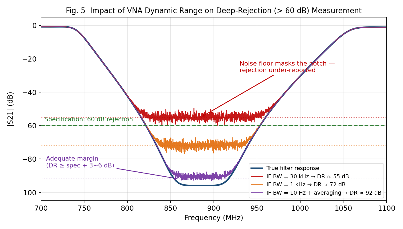
As a rule of thumb, the VNA dynamic range should exceed the maximum attenuation specification of the device under test by at least 3–6 dB. For a 60 dB rejection target, allowing for measurement tolerance, a dynamic range of roughly 100–120 dB is normally recommended. Most modern VNAs provide about 120 dB and can meet this requirement, but precision measurement still calls for attention to the settings listed in Table 4. [21][22]
| Method | Mechanism | Benefit | Cost |
|---|---|---|---|
| Reduce IF bandwidth | Narrower IF bandwidth lowers the receiver noise floor | About 10 dB per decade of reduction | Longer sweep time |
| Averaging | Averaging repeated sweeps suppresses random noise | Reduces random error | Increased measurement time |
| Raise source power | Widens the gap between signal and noise floor | Directly increases dynamic range | Limited by the device power rating |
| Noise-floor extension | Algorithmically subtracts the receiver's own noise | About 12 dB of additional improvement | Available only on certain high-end analysers |
| Segmented sweep | Separate power and bandwidth settings for passband and stopband | Balances speed against accuracy | More complex configuration |
Where dynamic range is inadequate, the result shows either an artificially low stopband rejection value or noise-floor ripple on the trace, both of which invite misjudgement of the filter's true performance. Verification of deep-rejection specifications must therefore begin by confirming adequate instrument margin, and the measurement report should record the IF bandwidth, averaging count and source power used. [19][22]
7. Conclusions: Selection and Customisation Guidelines
7.1 Findings
This study of cavity bandstop filters with sharp attenuation skirts reaches the following conclusions:
- (1)The shape factor is the common language of specification. For a bandstop filter it is computed as the 3 dB bandwidth divided by the 60 dB bandwidth — the inverse of the bandpass convention. The six-pole configuration here gives 2.43, a useful reference for most adjacent-band suppression scenarios.
- (2)Adding poles yields diminishing returns. Table 1 shows the shape factor improving sharply from 30.1 at N = 2 to 2.38 at N = 6, but only to 1.98 at N = 7 and 1.74 at N = 8, while passband insertion loss and tuning difficulty continue to rise.
- (3)Transmission zeros are the more efficient route. Where cavity count is constrained, cross-coupling or multi-network coupling delivers both a steeper skirt and a deeper, flatter stopband (Fig. 3).
- (4)Cascades require joint optimisation. With a stopband reflection coefficient near unity, a bandstop filter cascaded with an LPF or HPF must be optimised as a complete multi-stage structure to avoid inter-stage reflection degrading the passband.
- (5)Measurement dynamic range is a precondition of verification. Insufficient range systematically under-reports rejection depth (Fig. 5) and can cause conforming parts to be rejected.
7.2 Selection and Customisation Guidelines
When selecting or customising a cavity bandstop filter, the decision sequence in Table 5 is recommended.
| Step | Decision | Recommended action |
|---|---|---|
| 1 | Define stopband centre and rejection depth | State the notch centre frequency and required rejection (e.g. ≥ 60 dB), and note whether the application is reflective |
| 2 | Derive shape factor and transition bandwidth | Work back from the spacing between protected and interfering bands to an acceptable shape factor, and hence the cavity count |
| 3 | Assess the need for cascading | If a single bandstop structure gives insufficient stopband width or far-out attenuation, evaluate a composite LPF/HPF cascade |
| 4 | Select the transmission-zero strategy | Prefer cross-coupling or multi-network coupling for the steepest skirt and deepest stopband at a given cavity count |
| 5 | Confirm power and reflection conditions | Verify that the source or preceding isolator tolerates near-total in-band reflection; assess local field concentration at high power |
| 6 | Plan measurement verification | Confirm VNA dynamic range exceeds maximum attenuation by 3–6 dB, and fix the IF bandwidth and averaging settings |
Finally, customisation specifications should be derived backwards from the application. For public-safety interference mitigation, prioritise a narrowband high-rejection design (such as the TEMWELL series with rejection above 60 dB and insertion loss within 2.0 dB), and confirm that the passband range covers every adjacent signal interval requiring protection — only then will the deployed system deliver the expected isolation. [4][5]
7.3 TEMWELL's Production-Ready Capabilities
Drawing together the design, cascading and measurement themes above, Table 6 summarises five TEMWELL capabilities in cavity bandstop filters that are production-ready today and map directly onto customer value.
| Capability | Technology / product line | Deliverable customer value |
|---|---|---|
| High-Q cavity structure design | Standard Cavity Bandstop Filter series (760/885/1025/1190 MHz) | Rejection above 60 dB with insertion loss within 2.0 dB, directly matching public-safety BDA requirements |
| Cross-coupling and transmission-zero synthesis | Coupling-matrix synthesis plus HFSS eigenmode extraction | Improved shape factor without additional cavities, reducing volume and cost |
| Composite filter integration | Joint optimisation of bandstop cascaded with LPF/HPF | Notch and harmonic suppression delivered together, reducing inter-stage matching risk |
| Precision tuning SOP and automated production | Automated tuning stations with unit-by-unit S-parameter verification | Consistent specification compliance in volume, with a 7–10-day standard custom lead time |
| Deep-rejection measurement capability | VNA measurement procedure and setting standards with adequate dynamic range | Avoids yield misjudgement and customer complaints caused by under-reported rejection |
TEMWELL, headquartered in Taipei with more than 25 years of RF filter design and manufacturing experience and partners in over 20 countries, offers a complete portfolio of cavity, helical, SMD ceramic and SAW filters together with diplexers, duplexers and multiplexers. The bandstop design and measurement methods presented here map directly onto TEMWELL's current engineering and production capabilities, with customised delivery within a 7–10-day lead time.
Appendix - Complete source FAQ
FAQ: Cavity Bandstop Filters with Sharp Attenuation Skirts (A-08)
This FAQ is derived from the theoretical model, the specifications in Tables 1–6 and the simulated results in Figs. 1–5 of this article (No. A-08). Unless otherwise noted, all figures quoted are TEMWELL published product specifications or modelled responses based on a six-pole Chebyshev bandstop prototype — they are not production test reports.
Category 1 — Specifications and Design
-
What frequency bands and stopband width does this bandstop design cover?
The representative design point is f0 = 885 MHz with a 820–950 MHz stopband (60 dB rejection bandwidth ≈ 130 MHz, about 14.7% fractional bandwidth), flanked by passbands of DC–738 MHz and 1042–3500 MHz. The TEMWELL Standard Cavity Bandstop Filter line also offers 760 / 1025 / 1190 MHz centre frequencies, with the overall specification range spanning DC to 60 GHz and bandwidths from 1 MHz to 40 GHz.
Note: The model uses a six-pole Chebyshev bandstop prototype with 0.05 dB passband ripple and FBW = 0.393, giving BW3dB = 310 MHz, BW60dB = 128 MHz and a shape factor of 2.43 (Fig. 2). -
What are the power rating and impedance conditions?
Both 50 Ω (communications) and 75 Ω (CATV) system impedances are available, with N, SMA, SMD and needle connector options, and passband VSWR ≤ 2.0. Power handling depends on cavity size and connector type; in public-safety BDA applications, transmitters typically operate at 50 W (+47 dBm) to 100 W (+50 dBm).
Note: Within the stopband the filter behaves as a virtual short across the transmission line: the rejected energy is almost entirely reflected back to the source rather than absorbed. High-power applications must confirm that the source — or a preceding circulator or isolator — can tolerate a near-total-reflection load. -
Under what conditions were the quoted insertion loss and rejection obtained?
The insertion loss ≤ 2.0 dB, stopband rejection ≥ 60 dB and VSWR ≤ 2.0 given in Table 3 are TEMWELL published product specifications. The S-parameter curves in Figs. 1–5 are modelled responses based on a six-pole Chebyshev bandstop prototype (0.05 dB passband ripple); they are design illustrations, not production test reports.
Note: Verification requires unit-by-unit VNA measurement. Rejection specifications above 60 dB must be measured with adequate dynamic range — at least 3–6 dB above the maximum attenuation under test — otherwise the result is masked by the instrument noise floor (Fig. 5). -
What are the main advantages over PCB, SAW or BAW filters?
A cavity bandstop filter uses air as its transmission medium, giving a rugged structure, stable and reliable performance, high Q, good heat dissipation and higher-order spurious passbands located far from the main response. This allows more than 60 dB of rejection within a stopband only 130 MHz wide while holding passband insertion loss below 2.0 dB — a combination that SAW, BAW and planar filters cannot presently achieve simultaneously.
Note: The trade-off is larger volume and higher machining cost. The milled multi-cavity block — arguably the single most significant manufacturing advance of the past thirty years — substantially reduces size while preserving performance. -
Under what conditions does performance degrade noticeably?
Three cases dominate: (a) when the interferer sits very close to the protected frequency, skirt steepness is bounded by the achievable unloaded Q and the transition band cannot be narrowed indefinitely; (b) selectivity vanishes rapidly away from the notch centre — the filter attenuates only over a very narrow band; (c) when cascaded with lowpass or highpass filters, inter-stage impedance mismatch produces passband ripple and degraded insertion loss.
Note: Point (b) is the most commonly misunderstood limitation: a bandstop filter is not a broadband attenuator. Sites with multiple co-located transmitters, or several receivers in the same band, should use a bandpass solution instead.
Category 2 — Applications and Selection
-
Which equipment and applications is this filter best suited to?
The classic case is the front end of bidirectional amplifiers (BDAs) and DAS in public-safety communications (700/800 MHz police, fire and EMS networks), suppressing adjacent commercial cellular bands such as 800 SMR or LTE Band 14. Other common scenarios include duplex interference suppression in base stations, image-noise removal in radar, adjacent-channel protection in broadcasting, and spectrum cleanup in multi-band coexistence environments.
Note: A further practical use is transmitter sideband-noise reduction: a notch filter can attenuate only a few hundred kHz from the carrier, whereas a bandpass filter typically needs more than 1 MHz of guard band — and sometimes several cascaded stages — for the same effect. -
How can the design be adjusted for a narrower or wider stopband?
Stopband width is set by the fractional bandwidth FBW and the inter-cavity coupling coefficients, while skirt steepness is governed by the pole number N and the transmission-zero configuration. The N = 6, FBW = 0.393 case here gives a shape factor of 2.43; raising N to 7 reduces it to about 1.98 at the cost of higher passband insertion loss. A narrower stopband requires both higher unloaded Q and a reduced FBW.
Note: For a wide and deep stopband without sacrificing skirt steepness, use multi-network coupling to introduce two or three transmission zeros and form a flat deep stopband. One reported design achieves 46 / 55 / 53 dB rejection at three zeros placed at 1.39 / 2.14 / 2.89 GHz, with 87.3% fractional bandwidth at the 20 dB rejection level. -
What extra requirements apply in high-power or high-temperature environments?
Reflection is the critical issue at high power. At the notch centre the impedance approaches 0 Ω, forming a virtual short across the line; only a small fraction of the energy is dissipated in the cavity and the remainder is reflected to the source. The system must be able to tolerate this near-total reflection, and local field concentration caused by the standing wave must be considered.
Note: Thermally, high-Q narrow-stopband designs are the most sensitive to frequency drift: the narrower the stopband, the more likely a small centre-frequency shift will either pull the protected band into attenuation or let the interferer escape the stopband. Allow adequate guard band, or specify low-expansion materials and temperature-compensating structures. -
How much volume or mounting space should be reserved in space-constrained designs?
Cavity size scales inversely with centre frequency and directly with the required Q. Increasing cavity diameter raises the mechanical Q and improves selectivity without significantly increasing insertion loss — the most direct trade between mechanical size and electrical performance. Note that this is a design change, not a field adjustment.
Note: Where space is tight, a milled multi-cavity block — computer-designed and machined directly from solid aluminium — is far smaller than traditional phased-together individual cavities. Actual dimensions must still be assessed case by case from f0, rejection depth and pole count.
Category 3 — Customisation and Engagement
-
What specification data is needed to start a custom bandstop design?
Please provide: notch centre frequency and stopband range; required rejection depth (dB); the two passband ranges and the insertion-loss limit; VSWR or return-loss requirements; shape factor or transition bandwidth where applicable; power handling (noting whether the source tolerates near-total reflection); connector type and system impedance (50 Ω / 75 Ω); and mounting-space limits and operating temperature range.
Note: The rejection-depth-plus-transition-bandwidth pair is what determines cavity count and coupling complexity; stating it clearly at the enquiry stage materially shortens the specification cycle. -
How long from specification freeze to first samples?
TEMWELL's standard lead time for custom high-Q cavity products is 7–10 days, subject to specification complexity and current capacity.
-
What reliability or qualification testing is performed before volume production?
Production uses automated tuning stations together with a precision tuning SOP, with unit-by-unit S-parameter verification covering passband insertion loss, stopband rejection depth and VSWR, ensuring consistent compliance in volume.
Note: Deep-rejection (≥ 60 dB) verification imposes an additional instrument requirement: confirm in advance that VNA dynamic range exceeds the specification by 3–6 dB, and reduce IF bandwidth, enable averaging or use segmented sweeps as required (see Section 6). -
If an existing design does not fully meet our needs, what help is available?
We can customise cavity count and coupling topology (in-line or cross-coupled), adjust the number and placement of transmission zeros, evaluate composite solutions cascaded with lowpass or highpass filters, and advise whether a bandstop, bandpass or pass-reject cavity is the right choice.
Note: Where transmit/receive isolation is also required, a notch duplexer architecture can be evaluated; TEMWELL's existing TETRA cavity duplexer and LTE low-PIM diplexer lines allow integrated single-source delivery.
Category 4 — Supplementary Questions
-
[Supplementary] How do I choose between a bandstop and a bandpass filter?
The deciding factors are the frequency spacing between interferer and protected signal, and how many bands need protection. Where the spacing is very small (down to a few hundred kHz) and the interferer is a single known narrowband source, the bandstop filter is the more precise and lower-loss solution. Where a site hosts multiple co-located transmitters or several receivers in the same band, bandstop selectivity disappears beyond the notch and a bandpass filter should be used.
Note: A pass-reject cavity offers both pass and reject characteristics, but neither the notch depth nor the passband response matches a dedicated bandstop or bandpass cavity — it is a compromise. -
[Supplementary] What VNA settings matter when measuring rejection above 60 dB?
Dynamic range should exceed the maximum attenuation under test by 3–6 dB. Most modern VNAs quote around 120 dB, nominally sufficient, but the achieved dynamic range depends strongly on the IF bandwidth setting. In order of effectiveness: reduce IF bandwidth, enable averaging, raise source power within the device's rating, and use segmented sweeps with separate passband and stopband settings.
Note: Some high-end signal analysers offer noise-floor extension, which can recover roughly a further 12 dB of effective noise floor. With insufficient dynamic range, the trace shows noise-floor ripple in the stopband and rejection depth is under-reported (Fig. 5). -
[Supplementary] How should multiple notches be planned for deeper or wider rejection?
If a single notch cavity provides insufficient depth or slope, the most direct approach is to cascade several notch cavities, which improves both depth and skirt slope. A more advanced approach uses cross-coupling or multi-network coupling to place one transmission zero either side of the stopband centre, producing a flat, deep dual-zero response (Fig. 3).
Note: If broadband attenuation is needed in addition to the notch, cascade a lowpass or highpass filter (Fig. 4): adding a 1.5 GHz lowpass, for example, yields roughly 60 dB of extra rejection at the third harmonic of the carrier (≈ 2655 MHz) without affecting notch depth or skirt steepness.
References
- Band-stop filter. Wikipedia.
- How We Compare Band Pass and Band Stop Filters. Q Microwave.
- Band Pass Filter vs Band Stop Filter: Use Cases and Benefits. Eureka / PatSnap.
- Using Filters on a Public Safety BDA to Ensure Optimal Performance. Comba Telecom.
- Standard Cavity Bandstop Filter. TEMWELL Corporation.
- What is Cavity Filter? TEMWELL Corporation.
- Filter Shape Factor and Selectivity. Knowles Precision Devices.
- Filter Shape Factor and Selectivity. RF Globalnet.
- Skirt Selectivity and Shape Factor.
- What are Filter Shape Factor and Bandwidth. RF Wireless World.
- Narrow-band absorptive bandstop filter with multiple signal paths. US Patent 7323955B2.
- S. Oruç, Electronically Tunable Microwave Bandstop Filter Design, METU, 2010.
- Fully Predictive Combline Filter Modeling. Microwave Journal.
- Design of a W-Band Band-Stop Cavity Filter Based on Multi-network Coupling. IWS 2023.
- Design of a Compact Wideband Bandstop Filter with Three Transmission Zeros. Microwave Journal.
- Taiwan Bandpass Cavity Filters Suppliers / Custom Cavity Filter. TEMWELL Corporation.
- H. Jamshidi-Zarmehri et al., Efficient Design Procedure for Combline Bandpass Filters.
- End-Coupled, Half-Wavelength Resonator Filters. NTU EMC.
- Agilent, Understanding and Improving Network Analyzer Dynamic Range.
- Understanding and Improving Network Analyzer Dynamic Range. Testworld.
- What Are Vector Network Analyzers? VNAs Explained. Tektronix.
- How to Estimate and Enhance the Dynamic Range of a VNA. All About Circuits.
- Increasing Dynamic Range.
- Using Noise Floor Extension in an X-Series Signal Analyzer. Keysight Application Note 5990-5340.
- dbSpectra TECHBOOK Series: RF Filters, Release 2.0, dbSpectra Inc., 2019.
- Xu Jing, Design of Narrow Band High Suppression Cavity Filter. International Journal of Computer Applications Technology and Research, Vol. 12, Issue 10, pp. 14–17, 2023. DOI: 10.7753/IJCATR1210.1002