

Thermal Effects on Insertion Loss Stability of High-Power Cavity Bandpass Filters
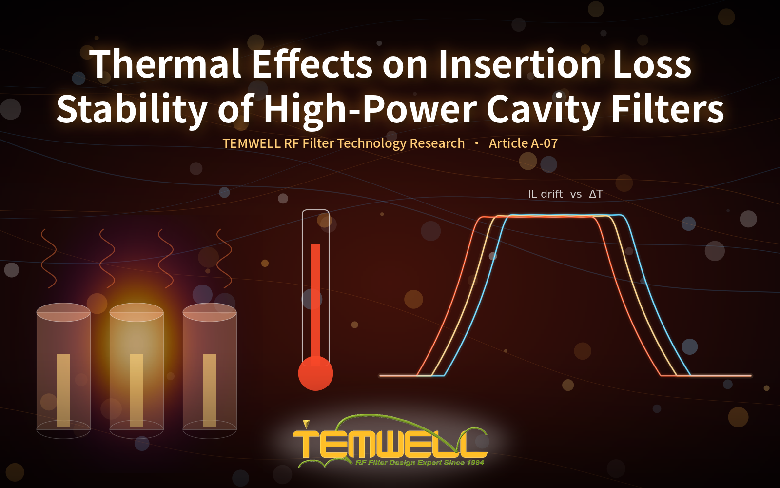
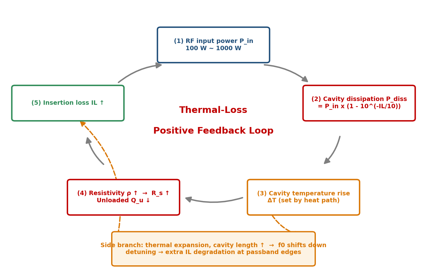
In RF systems delivering more than 10 W — typically 100 W to 1000 W — the insertion loss (IL) of a cavity bandpass filter is no longer a constant in the link budget but a quantity that varies with temperature. The filter's own insertion loss converts directly into heat; if the cavity cannot shed it, conductor resistivity rises with temperature, surface resistance follows as R_s ∝ √ρ, unloaded Q falls, and a positive feedback loop of "loss generates heat, heat raises resistance, resistance raises loss" is established. In parallel, thermal expansion of the cavity shifts the resonant frequency downward and produces additional IL degradation at the passband edges. This study decomposes both mechanisms, establishes a quantification method and measurement procedure for the insertion loss temperature coefficient (TC_IL, dB/°C), compares aluminium, copper and Invar 36 across electrical conductivity, thermal conductivity and thermal expansion, and proposes a hybrid thermal management strategy in which the body material handles heat removal while a compensation material stabilises dimensions. Referenced to IL(25 °C) = 0.80 dB, the analysis shows an uncompensated aluminium cavity has TC_IL of about 0.0035 dB/°C, giving an IL increase of 0.21 dB at 85 °C, whereas a copper cavity with silver plating and a heat sink reduces this to 0.0012 dB/°C (only 0.07 dB at 85 °C). A five-stage IL stability acceptance flow built on the MIL-STD-202G burn-in method is presented, together with four stability metrics that should be evaluated in addition to the room-temperature IL figure when selecting high-power cavity filters.
1. Introduction
1.1 Why thermal stability matters above 10 W
In RF applications above 10 W — high-power transmitters, broadcast equipment, satellite ground stations and military communication systems — a cavity bandpass filter must hold both a stable insertion loss and a controlled frequency drift. The Temwell Group high-power cavity bandpass filter series is designed for exactly this space, covering 500 MHz to 3 GHz at 100 W to 1000 W, with emphasis on maintaining a stable frequency response and rejection under high-power operation.
What separates these applications from low-power ones is that the filter's insertion loss is converted into heat that stays inside the cavity. Thermal drift that can be ignored at low power is amplified into a visible IL stability problem at high power. Bird Technologies' application engineering note makes the same point from the coupling side: the higher the insertion loss setting (the looser the coupling), the narrower the filtering but the greater the power loss converted to heat; in a high-power chain each cascaded cavity must dissipate its own share, and concentrating all the loss in one cavity risks overheating it.
1.2 Objectives
The objectives of this study are: (1) to separate the two physical paths by which heat acts on a high-power cavity filter — the temperature dependence of conductor resistivity, and detuning caused by thermal expansion; (2) to define the insertion loss temperature coefficient (TC_IL) together with its quantification and measurement procedure; (3) to compare common cavity materials across electrical conductivity, thermal conductivity and thermal expansion and derive a deployable thermal management strategy; (4) to construct a high-temperature ageing and IL stability acceptance flow consistent with industry standards; and (5) to summarise the stability data customers should request from suppliers when selecting high-power parts.
2. Thermal Mechanisms: Conductor Resistivity and Thermal Expansion
2.1 The heat source is the insertion loss itself
The heat source in a high-power cavity filter is its own insertion loss. The fraction of input power P_in that does not pass through the filter is dissipated inside the cavity:
Table 1 applies this expression across power levels and IL values. A 1000 W input with IL = 0.8 dB requires the cavity to dissipate about 168 W — the thermal output of a small space heater. Without an adequate heat path, cavity temperature climbs rapidly.
| Input power P_in | IL = 0.5 dB | IL = 0.8 dB | IL = 1.0 dB | IL = 1.5 dB |
|---|---|---|---|---|
| 100 W | 10.9 W | 16.8 W | 20.6 W | 29.2 W |
| 300 W | 32.6 W | 50.5 W | 61.7 W | 87.6 W |
| 500 W | 54.4 W | 84.1 W | 102.8 W | 146.0 W |
| 1000 W | 108.7 W | 168.2 W | 205.7 W | 292.1 W |
Once this heat raises the cavity temperature, it feeds back into the insertion loss along two paths — the positive feedback loop and the thermal expansion side branch shown in Figure 1.
2.2 Skin effect and the temperature dependence of resistivity
The insertion loss of a cavity filter is governed primarily by the unloaded quality factor Q_u, which in turn depends on conductor surface resistance and the skin effect. RF current is confined to a very thin skin depth:
where δ is skin depth, ρ resistivity, f operating frequency, μ0 the permeability of free space and μr the relative permeability of the conductor. For copper at 2.4 GHz the skin depth is only about 1.33 μm, so current flows almost entirely in the outermost layer. Surface condition — plating, roughness, oxidation — and surface resistance therefore dominate IL far more than bulk material thickness.
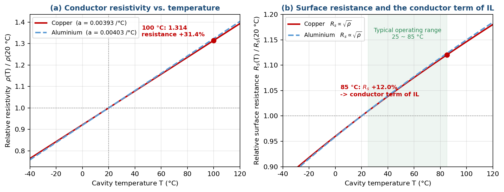
As cavity temperature rises under high-power loss, conductor resistivity increases with it. The temperature coefficient of resistance is about 0.00393 per °C for copper (referenced to 20 °C) and about 0.00403 for aluminium. Mullard measurement data show that with copper wire resistance at 20 °C taken as unity, the coefficient rises to 1.314 at 100 °C — an increase of about 31.4%. Since cavity loss is proportional to surface resistance and R_s ∝ √ρ, a 31.4% rise in resistivity corresponds to about a 14.6% rise in surface resistance, driving insertion loss up directly (Figure 2).
2.3 Thermal expansion, cavity dimensions and resonant frequency
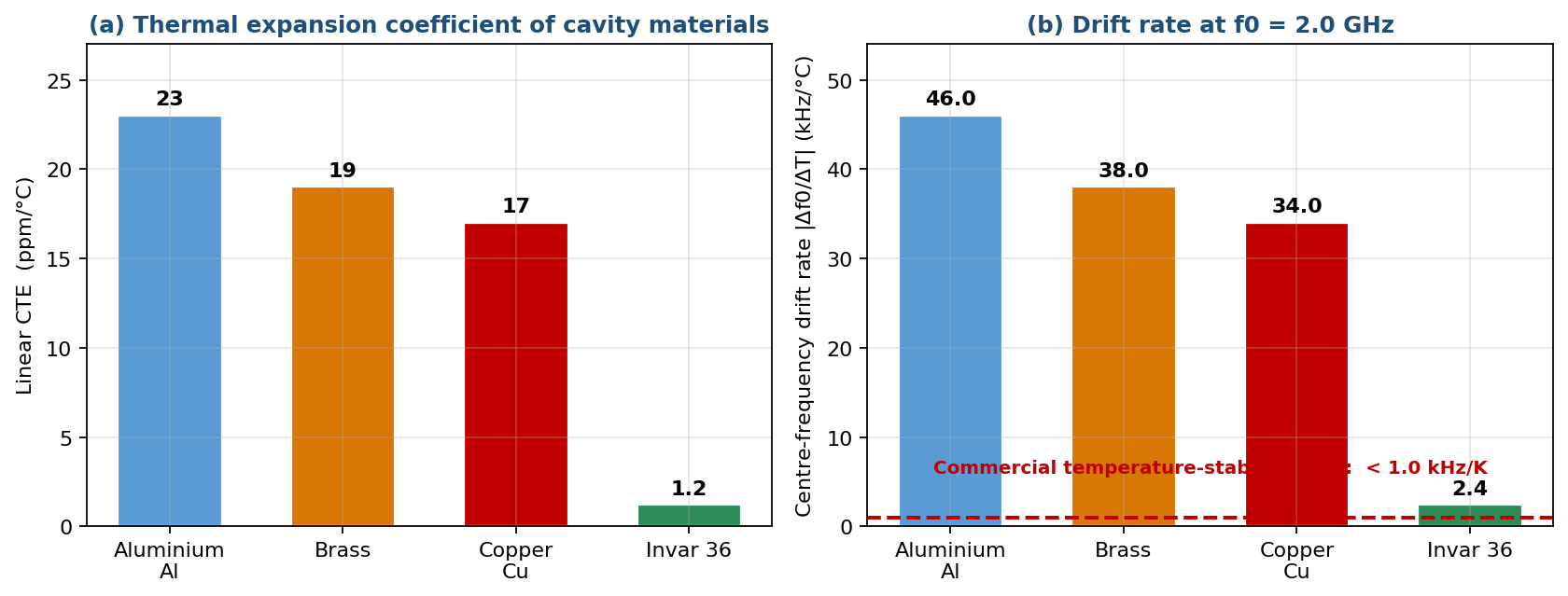
Rising temperature simultaneously changes cavity dimensions through thermal expansion. Cavity resonant frequency is inversely related to physical size, so an expanding cavity shifts its resonance downward, moving the designed coupling state off the centre frequency and producing additional insertion loss at the passband edges or centre. The linear coefficients of thermal expansion (CTE) of common metals differ substantially, as shown in Table 2.
| Material | CTE (ppm/°C) | Characteristics |
|---|---|---|
| Aluminium and alloys | approx. 21–24 | Highest CTE; light weight, low cost |
| Brass | approx. 19–20 | Between aluminium and copper |
| Copper | approx. 17–18 | Excellent electrical and thermal conductivity, still expands noticeably |
| Invar 36 | approx. 1.2 (near zero) | Purpose-designed for low expansion; used in high-stability compensation structures |
Converting CTE into a frequency drift rate reveals the magnitude of the problem: at f0 = 2.0 GHz, an aluminium cavity drifts about 46 kHz/°C downward, a copper cavity about 34 kHz/°C, and Invar 36 only about 2.4 kHz/°C. Measured against the "temperature stability < 1.0 kHz/K" figure quoted for a commercial DAB six-pole bandpass filter, neither pure aluminium nor pure copper reaches the specification without compensation — which is precisely why temperature-compensation structures exist (Figure 3).
US Patent US6529104B1 describes exactly this approach: a control-rod structure combining materials of differing thermal expansion coefficients constrains deformation of the cavity surface at selected points, compensating the resonant frequency drift caused by thermal expansion. The idea of restraining a high-expansion body with a low-expansion member forms the theoretical basis of the hybrid strategy in Section 4.
3. Quantifying Insertion Loss Drift: Temperature Coefficient Method
3.1 Definition
The industry quantifies the sensitivity of insertion loss to temperature through the insertion loss temperature coefficient (TC_IL), defined analogously to the frequency temperature coefficient:
where ΔIL is the change in insertion loss measured over the temperature interval ΔT. TC_IL is a composite quantity containing two mechanisms. The conductor term (rising resistivity) is usually gradual and predictable from the √ρ model; the detuning term (f0 shift from thermal expansion) depends strongly on bandwidth and passband shape and is often dominant in narrowband designs.
3.2 Measurement and regression procedure
The recommended engineering procedure is: measure S21 in a temperature chamber at several set points (for example −40 °C, 0 °C, 25 °C, 60 °C and 85 °C) after soaking at each; record the minimum passband insertion loss at each point; and obtain the slope by least-squares linear regression, giving the average IL temperature coefficient over the target range. The same data set yields Δf0/ΔT simultaneously, which serves as a direct indicator of whether the thermal expansion compensation is effective.
3.3 Reference benchmarks
Published data usable as quantitative benchmarks include the following. In measurements of an LTCC (low-temperature co-fired ceramic) temperature-compensated filter, the frequency temperature coefficient after compensation was reduced to 1.85 ppm/°C (from −69.5 ppm/°C uncompensated), while insertion loss varied by about 0.46 dB over −50 °C to 80 °C, equivalent to an average coefficient of roughly 0.0035 dB/°C. A second reference is a commercial DAB six-pole bandpass filter whose temperature stability is specified as frequency drift below 1.0 kHz/K, with separate insertion loss limits at different frequencies (< 1.10 dB at 174 MHz, < 1.30 dB at 230 MHz).
This shows that commercial products typically constrain thermal stability through a pair of specifications — a frequency drift rate together with an insertion loss ceiling — rather than a single direct TC_IL value. Note that LTCC and conventional metal cavities differ in thermal behaviour, so these values serve only as an order-of-magnitude reference; the TC_IL of an actual metal cavity must be obtained by measurement. Figure 4 compares the IL drift trajectories of three thermal management configurations from −40 °C to +85 °C, referenced to IL(25 °C) = 0.80 dB.
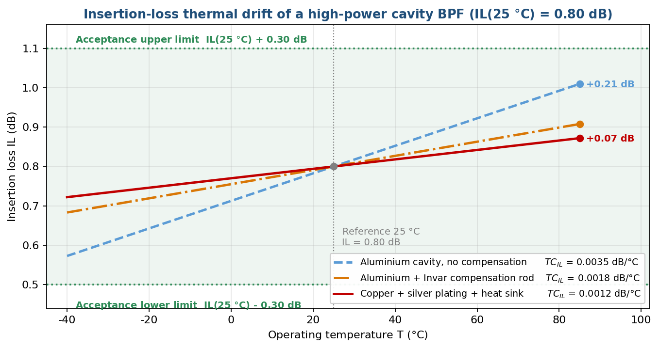
| Thermal management configuration | TC_IL (dB/°C) | ΔIL at 85 °C | ΔIL at −40 °C | ±0.30 dB acceptance |
|---|---|---|---|---|
| Aluminium cavity, no compensation | approx. 0.0035 | +0.21 dB | −0.23 dB | Pass, but little margin |
| Aluminium + Invar compensation rod | approx. 0.0018 | +0.11 dB | −0.12 dB | Pass |
| Copper + silver plating + heat sink | approx. 0.0012 | +0.07 dB | −0.08 dB | Pass with ample margin |
4. Thermal Management Design: Heat Removal Structure and Material Selection
4.1 A three-way material trade-off
Thermal management design is a balance between material selection and heat path planning. Aluminium, copper and Invar each have strengths and weaknesses across electrical conductivity, thermal conductivity and thermal expansion, and no single material satisfies all three dimensions (Table 4).
| Material | Electrical conductivity | Thermal conductivity | Thermal expansion | Weight / cost | Typical use |
|---|---|---|---|---|---|
| Aluminium(usually silver-plated) | Moderate plating needed for surface conductivity | Good about half that of copper | High approx. 23 ppm/°C | Light / low | General high-power applications sensitive to weight and cost |
| Copper (usually silver-plated) | Excellent low surface resistance, high Q_u | Excellent about twice that of aluminium | Moderate approx. 17 ppm/°C | Heavy / high | Demanding IL requirements with a well-designed heat path |
| Invar 36 | Poor high resistivity | Poor | Very low approx. 1.2 ppm/°C | Moderate / high | Temperature compensation members (control rods), not the cavity body |
4.2 Surface plating: the thinnest layer sets the IL
As Section 2.2 shows, RF current flows only within the skin depth (about 1.33 μm for copper at 2.4 GHz), so cavity inner walls are usually silver-plated to raise conductivity and Q_u — silver has a lower surface resistance than bare copper or aluminium, reducing insertion loss and improving intrinsic efficiency before any heat removal is considered. The value of plating is that it lowers the heat source itself: a lower IL means a smaller P_diss and therefore a weaker starting point for the feedback loop.
4.3 Heat path and thermal resistance
In pure heat removal terms, the thermal conductivity of copper at room temperature is close to twice that of aluminium, so for the same geometry a copper cavity carries heat from the resonator inner wall to an external heat sink faster, reducing Q degradation from local hot spots. Copper is, however, denser and more expensive than aluminium, and although its CTE is lower it is still insufficient to suppress frequency drift on its own.
On the structural side, enlarging external fin area, adopting forced-air cooling, or coupling the cavity to a metal chassis with thermal grease are all direct means of reducing internal temperature rise and therefore compressing insertion loss drift. When cavities are cascaded, coupling settings should avoid concentrating loss in a single cavity, which would otherwise become a hot spot and detune first.
4.4 Hybrid strategy: separating heat removal from dimensional stability
Because of its near-zero thermal expansion, Invar is normally used as the key member of a temperature compensation structure rather than as the cavity body material. The compensation design of US Patent US6529104B1 uses an Invar control rod to limit the deformation range of the cavity surface under heat, cancelling frequency drift, rather than replacing aluminium or copper as the primary structural material.
This hybrid strategy — body material for heat removal, compensation material for dimensional stability — is standard engineering practice in high-power cavity filters, and is the main source of the reduction in Figure 4 of aluminium-cavity TC_IL from 0.0035 to 0.0018 dB/°C. Adding a copper cavity and forced cooling on top brings it down to the 0.0012 dB/°C class.
5. Temwell Test Standard: High-Temperature Ageing and IL Stability Acceptance
5.1 Industry burn-in baseline
Thermal stability verification of high-power RF components generally follows the industry-standard High Temperature Storage (HTS) and burn-in methods. Under military test standards such as MIL-STD-202G, components are energised and operated at an elevated temperature — typically 100 °C to 150 °C — for a defined period to accelerate the performance degradation seen over long service life. In a typical static burn-in flow, the component operates continuously at 125 °C for 168 hours, approximating about six months of field use.
5.2 Five-stage IL stability acceptance flow
For insertion loss stability acceptance of high-power cavity filters, the recommended flow comprises the five stages shown in Figure 5.
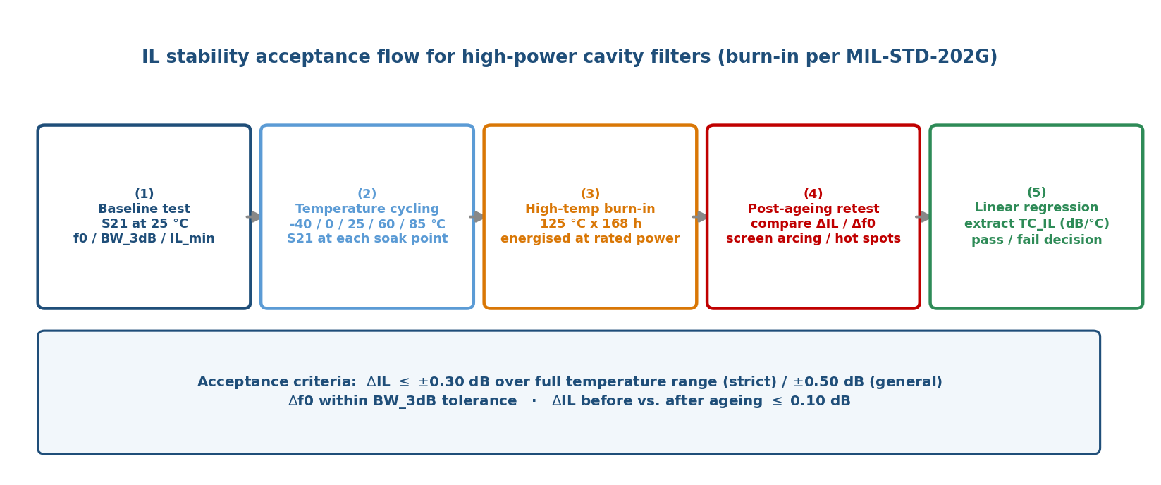
| Stage | Activity | Data obtained | Decision criterion |
|---|---|---|---|
| (1) Baseline | Measure S21 at 25 °C ambient | f0, BW_3dB, IL_min, S11 | Initial values meet design specification |
| (2) Temperature cycling | −40 / 0 / 25 / 60 / 85 °C measured after soaking | IL and f0 at each point | Whether ΔIL and Δf0 exceed limits |
| (3) Burn-in | Energised at rated power 125 °C × 168 h | Monitoring record during ageing | Abnormal temperature rise or arcing signs |
| (4) Post-ageing retest | Return to 25 °C, remeasure S21 and compare to baseline | ΔIL and Δf0 before/after | Degradation within allowance |
| (5) Regression | Linear regression on the temperature points | TC_IL (dB/°C) | Compared against the specified TC_IL limit |
5.3 Acceptance criteria
Acceptance is normally set as follows: the change in insertion loss across the whole operating temperature range must not exceed the design specification (±0.30 dB for demanding applications, ±0.50 dB in general, depending on the system link budget); frequency drift must remain within the allowed bandwidth tolerance; and ΔIL before versus after high-temperature ageing should be held within 0.10 dB. Abnormal degradation may indicate internal arcing or localised overheating.
The Temwell high-power cavity bandpass filter series is rated for 100 W to 1000 W with emphasis on stable frequency response and signal purity under high-power operation, meaning that its product design encompasses the thermal ageing and temperature cycling verification described above, so that insertion loss specifications remain consistent under the customer's actual deployment temperatures.
6. Field Considerations: Installation Temperature versus Specification
Insertion loss is normally measured and specified at a defined reference temperature such as 25 °C, yet real deployment environments vary considerably. The Temwell helical bandpass filter line, for example, has a standard operating temperature range of −30 °C to +75 °C but can be customised to −40 °C or +85 °C for extreme environments — an indication of how widely temperature tolerance requirements differ between outdoor base station enclosures, vehicular communication equipment and satellite ground stations.
6.1 Three field planning points
First, the internal temperature of an enclosure is often significantly above ambient because of other heat-generating components such as power amplifiers and power supply modules. Where a filter shares a sealed enclosure with a power amplifier, the actual operating temperature may exceed outdoor air temperature by 10 °C to 30 °C, pushing insertion loss up accordingly.
Second, mounting orientation and heat sink alignment affect convective efficiency. Vertical mounting with natural convection generally outperforms horizontal sealed mounting, and fin direction should follow the natural upward path of heated air.
Third, if the datasheet insertion loss was measured at 25 °C, selection should additionally verify whether the insertion loss at the maximum operating temperature of the deployment still meets the system link budget — otherwise, neglecting temperature correction can produce out-of-specification signal attenuation during summer peaks.
6.2 Temperature stack-up in four typical deployments
Figure 6 uses TC_IL = 0.0035 dB/°C (uncompensated aluminium cavity) to quantify, for four typical deployments, the actual operating temperature formed by stacking ambient temperature, enclosure temperature rise and the filter's own dissipation, together with the resulting IL increment.
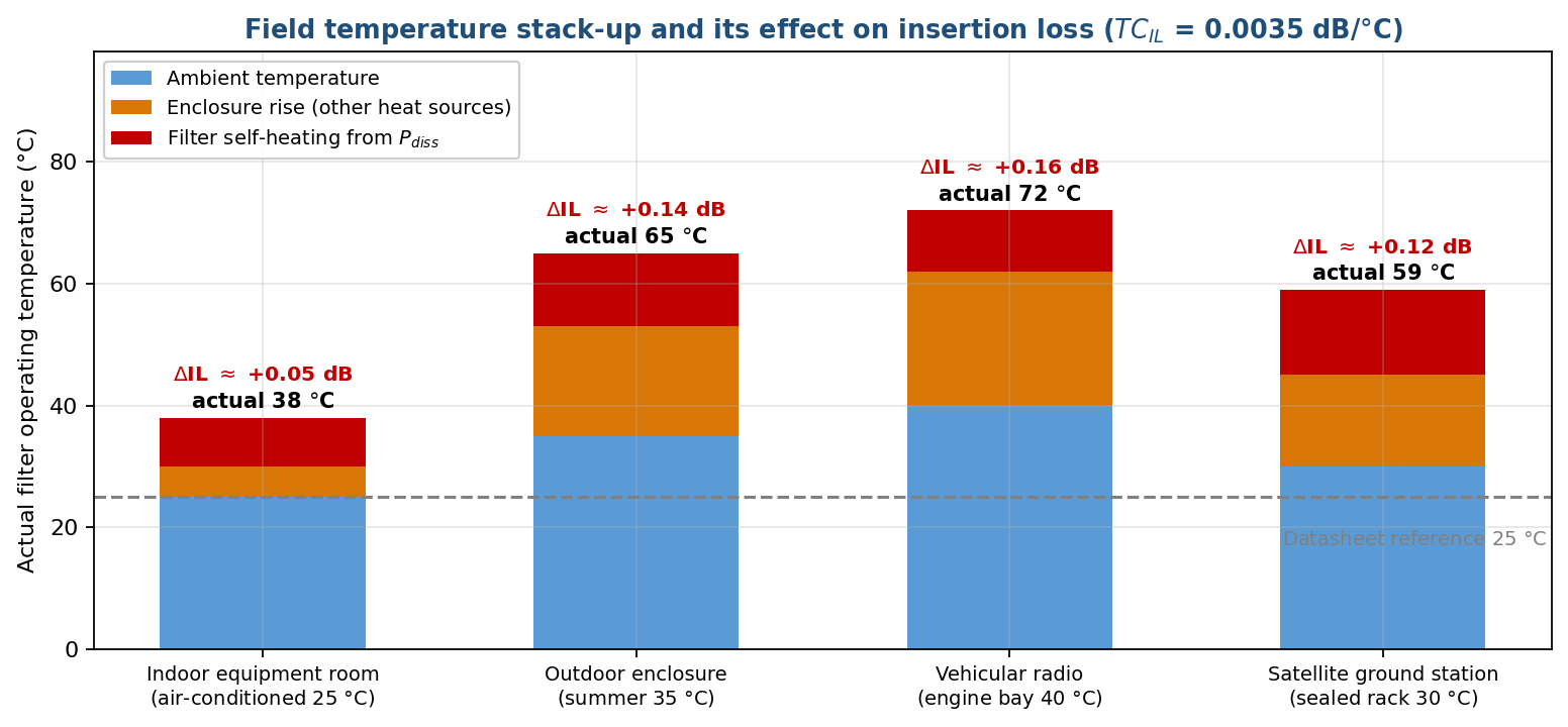
The conclusion is unambiguous: in the harshest vehicular case, the datasheet room-temperature IL and the IL under real operating conditions can differ by more than 0.16 dB. For high-power systems whose link budget margin is only a few dB, that gap is enough to cause marginal failure during summer heat.
7. Conclusions and Temwell R&D Capability
7.1 Conclusions
- Conclusion 1: The insertion loss of a high-power cavity filter is a thermally coupled dynamic quantity, not a constant. IL is itself the heat source (1000 W at 0.8 dB corresponds to about 168 W dissipated), and that heat in turn raises IL through increased resistivity, closing a positive feedback loop.
- Conclusion 2: Thermal effects act along two paths — the conductor term (ρ rises → R_s ∝ √ρ rises → Q_u falls) and the detuning term (thermal expansion → f0 shifts down → passband-edge degradation). In narrowband high-power designs the detuning term is often dominant.
- Conclusion 3: The insertion loss temperature coefficient TC_IL (dB/°C) should become a standard selection metric for high-power parts. Referenced to IL(25 °C) = 0.80 dB, an uncompensated aluminium cavity is about 0.0035 dB/°C, an Invar-compensated cavity about 0.0018 dB/°C, and a copper cavity with silver plating and a heat sink can reach 0.0012 dB/°C.
- Conclusion 4: No single material optimises electrical conductivity, thermal conductivity and thermal expansion simultaneously. The hybrid design — body material for heat removal, compensation material for dimensional stability — is the industry-standard solution.
- Conclusion 5: The datasheet room-temperature IL value cannot be entered into a link budget directly. The actual operating temperature is the sum of ambient temperature, enclosure temperature rise and self-heating, and typical outdoor and vehicular deployments run more than 40 °C above the 25 °C reference.
7.2 High-power selection checklist
Drawing the analysis together, the room-temperature insertion loss figure is only the starting point when selecting a high-power cavity bandpass filter. Engineers should additionally request the four items in Table 6 from the supplier.
| Checklist item | Data to request | Criterion |
|---|---|---|
| (1) Insertion loss temperature coefficient | TC_IL (dB/°C) or full-temperature S21 curves | Lower is better; ≤ 0.002 dB/°C is preferred |
| (2) Maximum IL deviation over range | ΔIL limit across the customer's actual temperature range | ΔIL must fit within the link budget margin |
| (3) Heat path and material set | Cavity material, plating, cooling structure, thermal simulation report | Whether thermal verification was done at this power level |
| (4) Ageing test data | Burn-in conditions and temperature-cycling S21 curves | ΔIL before versus after ageing ≤ 0.10 dB |
7.3 Temwell capabilities available today
| Capability | Related technology / product line | Customer value |
|---|---|---|
| High-power cavity design and manufacture | High Power Cavity BPF series, 500 MHz–3 GHz, 100 W–1000 W; aluminium and copper options with silver plating | Stable IL and frequency response at rated power |
| Thermal management and compensation structures | Fin design, thermal interface planning, low-expansion compensation members (Invar concept) | TC_IL reduced from 0.0035 to the 0.0018 dB/°C class |
| Full-temperature verification | Chamber cycling −40 to +85 °C; burn-in 125 °C × 168 h | Full-temperature S21 curves and a TC_IL regression report |
| Operating temperature customisation | Standard −30 to +75 °C, customisable to −40 to +85 °C | Covers outdoor enclosures, vehicular and satellite ground stations |
| Customisation lead time | Standard 7–10 days for customised high-Q cavities | Add 2–3 weeks where thermal verification reports are required |
7.4 Twelve-month R&D roadmap
- Establish an internal TC_IL measurement SOP and database, incorporating full-temperature S21 curves into the standard shipping report for high-power products.
- Introduce coupled thermal–electromagnetic simulation (HFSS together with thermal analysis) so that ΔIL and Δf0 are predicted at the design stage rather than corrected after measurement.
- Develop standard low-expansion compensation components, targeting TC_IL below 0.0018 dB/°C for high-power aluminium-cavity products.
- Build standard cooling solutions for the 500 W and above class (fins, cold plate, forced air) to shorten thermal design time on high-power custom projects.
- Extend the Temstron RF amplifier and passive component lines to offer customers enclosure-level thermal margin assessment and turn-key delivery of amplifier-plus-filter assemblies.
In summary, thermal stability assessment in high-power applications requires moving beyond the mindset of a single room-temperature datasheet figure toward a systematic verification logic spanning the full temperature range and the full product life. This is the core value proposition of the A-07 topic in high-power cavity filter positioning and in technical communication with customers.
Appendix - Complete source FAQ
FAQ — Thermal Effects on Insertion Loss Stability of High-Power Cavity Filters (A-07)
This FAQ is compiled from the thermal model, Tables 1–7 and Figures 1–6 of this paper (Article No. A-07). Unless otherwise noted, the figures quoted are analytical results, published measurement benchmarks, and Temwell production experience — not the measurement report of any single unit. Actual product specifications are governed by the shipping test report.
Category 1 — Technical specification and design
-
What frequency bands and bandwidths does this filter design mainly support?
This paper addresses the Temwell High Power Cavity Bandpass Filter series, covering 500 MHz to 3 GHz at power levels of 100 W to 1000 W; the thermal drift calculations use f0 = 2.0 GHz as the reference. In terms of bandwidth, high-power cavity filters are typically narrow to moderate band designs (fractional bandwidth roughly 1–5%). Because insertion loss is inversely proportional to bandwidth at a given unloaded Q, narrowband designs are the most temperature-sensitive — which is precisely why thermal stability matters so much for this product family.
-
What are the rated power and impedance conditions of this filter?
System impedance is 50 Ω, with rated CW power from 100 W to 1000 W. An important caveat: a power rating does not mean the filter runs cool. Per Table 1, a 1000 W input with IL = 0.8 dB forces the cavity to dissipate roughly 168 W of heat — that figure, not the power rating alone, is the real input to thermal design. When selecting a part, always ask the supplier for the dissipated power at rated input together with the permissible ambient temperature.
-
Under what measurement conditions were the insertion loss and return loss obtained?
The IL thermal drift curves in Figure 4 are referenced to IL(25 °C) = 0.80 dB, with S21 measured in a temperature chamber over −40 °C to +85 °C after soaking at each set point, and the slope extracted by linear regression. The three curves correspond to TC_IL values of 0.0035 / 0.0018 / 0.0012 dB/°C. The 0.0035 dB/°C figure is derived from published LTCC temperature-compensated filter measurements (0.46 dB IL variation over −50 °C to 80 °C). Because LTCC and metallic cavities behave differently thermally, the TC_IL of an actual metal cavity must still be established by measurement.
-
What are the main advantages of this structure over conventional designs such as PCB filters or
SAW/BAW?
A metallic cavity is currently the only structure that simultaneously delivers hundred-watt power handling and sub-dB insertion loss. SAW and BAW devices generally handle only watt-level power, while planar PCB filters face a double constraint at high power: insufficient Q due to substrate dielectric loss, and a poor heat path through very thin conductors. A further advantage of the metal cavity is that it is itself a heat sink — the cavity wall can be bolted directly to the chassis or a finned heat sink to conduct P_diss away, which planar structures cannot easily replicate.
-
Under what conditions does the performance degrade noticeably, and what should be watched for?
The classic failure mode is an interrupted heat path. Dissipated power raises the cavity temperature, which raises conductor resistivity (copper resistance rises about 31.4% at 100 °C relative to 20 °C), which raises surface resistance by about 14.6% since R_s ∝ √ρ; unloaded Q falls, IL rises further, and the positive feedback loop of Figure 1 closes. If the heat cannot escape, the loop accumulates until thermal runaway. A second, frequently overlooked mechanism is detuning through thermal expansion: an aluminium cavity with a CTE of about 23 ppm/°C shifts down roughly 46 kHz/°C at f0 = 2.0 GHz, and in narrowband designs the resulting passband-edge degradation often exceeds the conductor term itself.
Category 2 — Application scenarios and product selection
-
Which equipment or applications is this filter best suited to?
It suits links delivering more than 10 W — typically 100 W to 1000 W — such as high-power transmitters, broadcast equipment, satellite ground stations, radar and military communication systems. What these share is high transmit power combined with co-location of the filter and power amplifier inside a single enclosure, so ambient temperature and self-heating stack up. Thermal stability is therefore as important a selection criterion as the room-temperature IL figure.
-
If I need a narrower or wider bandwidth, how can this design be adjusted?
Bandwidth is set by coupling coefficient and pole count, but at high power there is an extra thermal cost to weigh. Narrowband designs have higher IL and greater heat dissipation, and are more sensitive to thermally induced f0 drift — as Δf0 grows relative to BW_3dB, passband-edge IL degradation is amplified. If a customer requires narrower bandwidth, we recommend upgrading thermal management in parallel (copper cavity or larger heat sink) or adding an Invar compensation structure to bring TC_IL below 0.0018 dB/°C. Wider bandwidth reduces thermal sensitivity but raises the baseline IL, which increases dissipation — both effects must be assessed together.
-
Are there additional requirements or limitations in high-power or high-temperature
environments?
Three additional requirements. First, provide the actual installed ambient temperature limit and enclosure cooling conditions rather than simply citing the standard −30 °C to +75 °C datasheet range (Temwell can customise to −40 °C or +85 °C). Second, ensure a low thermal-resistance interface between cavity and chassis — thermal grease, metal-to-metal clamping or a heat sink — to avoid heat accumulating in a single cavity. Third, when several cavities are cascaded each must dissipate its own share; if the coupling settings concentrate loss in one cavity, that cavity will overheat first. Per Figure 6, an outdoor enclosure in summer can put the filter at 65 °C, corresponding to ΔIL of about +0.14 dB, and the link budget must reserve that margin.
-
For space-constrained designs, how much volume or installation clearance should be reserved?
The volume of a high-power cavity filter is driven mainly by power level and frequency band, but in space-constrained cases the real constraint is usually heat-dissipating area rather than the body dimensions: the heat sink and its convection clearance must be counted in. In practice, reserve enough margin around the cavity body to mount fins, and orient the installation to work with natural convection (vertical mounting outperforms horizontal sealed mounting). If passive cooling genuinely cannot be accommodated, move to forced-air cooling or a cold plate, and include TC_IL and the permissible ΔIL in the requirement set from the specification stage.
Category 3 — Customisation and engagement process
-
What specification data should be prepared to customise a similar filter?
Beyond the standard items — centre frequency f0, 3 dB bandwidth, IL limit, S11 requirement, out-of-band rejection, system impedance and connector type — high-power projects need five additional thermal inputs: (1) rated and peak input power and duty cycle (CW or pulsed); (2) actual operating temperature range and estimated enclosure temperature rise; (3) permissible ΔIL and Δf0 over the full temperature range; (4) available cooling conditions (natural convection, forced air, cold plate) and the mounting interface that can be provided; (5) whether burn-in, temperature cycling or other reliability qualification is required, and to which standard.
-
How long does it take from specification sign-off to the first samples?
Temwell's standard lead time for customised high-Q cavity products is 7–10 days. If temperature-cycling and burn-in reports are also required, qualification time must be added: per the MIL-STD-202G static burn-in method, 125 °C × 168 h alone takes 7 days, and with soak-point measurements across the temperature cycle a complete thermal stability report should be planned for an additional 2–3 weeks.
-
What reliability or qualification testing is performed before mass production?
The five-stage flow of Figure 5 is followed: (1) baseline measurement at 25 °C (f0, BW_3dB, IL_min); (2) temperature cycling at −40 / 0 / 25 / 60 / 85 °C with S21 measured after soaking at each point; (3) high-temperature burn-in at 125 °C for 168 h energised at rated power (per MIL-STD-202G, approximating about six months of field service); (4) post-ageing retest comparing ΔIL and Δf0 and screening for internal arcing or local overheating; (5) linear regression across the temperature points to extract TC_IL for the pass/fail decision. Acceptance is ΔIL ≤ ±0.30 dB over the full range (strict) or ±0.50 dB (general), Δf0 within the BW_3dB tolerance, and ΔIL before versus after ageing ≤ 0.10 dB.
-
If an existing design does not fully meet the requirement, what adjustments or evaluation support can
be offered?
Adjustment is possible at three levels. Material: switch from aluminium to copper (roughly double the thermal conductivity) and silver-plate the inner walls to lower surface resistance. Structure: introduce an Invar 36 compensation rod, using a near-zero-expansion member to restrain cavity deformation under heat and cancel f0 drift — the compensation concept described in US Patent US6529104B1. System: enlarge fin area, move to forced-air cooling, or couple the cavity to the metal chassis with thermal grease. Temwell can also estimate the operating temperature and expected ΔIL from the customer's actual enclosure conditions, completing the thermal margin assessment before the design is frozen.
Category 4 — Supplementary questions
-
[Supplementary] How is the insertion loss temperature coefficient TC_IL calculated and
accepted?
It is defined as TC_IL = ΔIL / ΔT, in dB/°C. In practice, measure S21 in a temperature chamber at five points (−40 / 0 / 25 / 60 / 85 °C) after soaking, take the minimum passband insertion loss at each point, and apply linear regression; the slope is the average TC_IL over the target range. Note that commercial datasheets rarely state TC_IL directly — they usually constrain thermal stability with a pair of specifications, a frequency drift rate (for example < 1.0 kHz/K) plus an insertion loss ceiling. When selecting a part, actively request the full-temperature S21 curves rather than a single room-temperature value.
-
[Supplementary] How should aluminium, copper and Invar be traded off?
They are not mutually exclusive options but a division of labour. Aluminium alloy is light, low-cost and thermally sound (about half the conductivity of copper) but has the highest CTE at roughly 23 ppm/°C; it suits weight- and cost-sensitive high-power applications and is usually silver-plated to improve surface conductivity. Copper offers superior electrical and thermal conductivity (about twice the thermal conductivity of aluminium) with a CTE near 17 ppm/°C, suiting demanding IL requirements where the heat path is well designed, at the cost of weight and price. Invar 36 has an extremely low CTE (about 1.2 ppm/°C) but poor electrical and thermal conductivity, so the industry-standard approach is a hybrid: the body material handles heat removal while an Invar compensation rod stabilises dimensions — Invar is not used for the whole cavity..
-
[Supplementary] Can the datasheet IL value be used directly in a link budget?
Not advisable. Datasheet IL is normally measured at 25 °C, whereas the deployed operating temperature is the sum of ambient temperature, the rise caused by other heat sources in the enclosure (amplifiers, power supplies) and the filter's own P_diss. Per Figure 6, an outdoor enclosure in summer can reach 65 °C and a vehicular engine-bay installation 72 °C — more than 40 °C above the 25 °C reference — corresponding to ΔIL of about +0.14 dB and +0.16 dB respectively. The correct approach is to use the IL at the maximum operating temperature in the link budget, and to keep at least a factor of one in reserve for thermal drift.
References
- Bird Technologies, "Insertion Loss in Cavity Filters — Application Engineering Note," on the relationship between coupling loop setting and cavity heat dissipation.
- Temwell Group, "High Power Cavity Bandpass Filter — Product Series," 500 MHz – 3 GHz / 100 W – 1000 W standard product specifications, https://www.temwell.com.
- Omni Calculator / Pasternack, "Skin Depth Calculator & RF Skin Effect Calculator," copper skin depth ≈ 1.33 μm at 2.4 GHz.
- Mullard Ltd., "Conductor Resistance vs. Temperature Data," copper resistance coefficient 1.000 at 20 °C reference, 1.314 at 100 °C.
- Engineering ToolBox, "Metals — Temperature Expansion Coefficients," aluminium 21–24, brass 19–20, copper 17–18 ppm/°C.
- E. Aldalur et al., "Thermal Expansion Behaviour of Invar 36 Alloy Parts Fabricated by Additive Manufacturing," Journal of Materials Research and Technology, 2022.
- US Patent US6529104B1, "Temperature Compensated High Power Bandpass Filter," control rod combining materials of differing thermal expansion to compensate cavity resonant frequency drift.
- "Temperature Compensated Bandpass Filters in LTCC," frequency temperature coefficient 1.85 ppm/°C after compensation (−69.5 ppm/°C uncompensated); IL variation about 0.46 dB over −50 to 80 °C./li>
- "DAB 6-Pole 80 mm Bandpass Filter TS6D80R — Datasheet," temperature stability < 1.0 kHz/K; IL < 1.10 dB at 174 MHz, < 1.30 dB at 230 MHz.
- MIL-STD-202G, "Test Methods for Electronic and Electrical Component Parts — Burn-in / High Temperature Storage," static burn-in 125 °C × 168 h.
- "Comparison of Copper and Aluminum as the Thermal Link Material," thermal conductivity of copper approximately twice that of aluminium.
- "Practical Notes About Cavity Filters," coupling loop settings and the distribution of loss across cascaded cavities.
- "Application — Test and Validate the Performance of Cavity Band Pass Filters," temperature cycling and S21 verification procedure.
- Temwell Corporation, "RF Helical Bandpass Filter — Comprehensive Guide," standard operating temperature −30 to +75 °C, customisable to −40 / +85 °C.
- Temwell Corporation, Product Catalog & Technical Datasheets, https://www.temwell.com, 2026.