

Bandwidth Optimization of 5G Cavity Bandpass Filters
Abstract
5G New Radio (NR) places unprecedented demands on the front-end bandpass filters of macro-cell base stations: single-carrier bandwidth (BW) can reach 100 MHz in Sub-6 GHz (FR1) and 400 MHz in millimeter-wave (FR2), while the link budget requires insertion loss (IL) on the order of 0.5 dB or less. This paper presents a systematic study of bandwidth optimization in 5G cavity bandpass filters. A trade-off model is established among BW, IL and out-of-band skirt steepness, and the key design variables — pole number (N), coupling coefficient (k), unloaded cavity Q (Qu) and transmission zeros (TZs) — are analyzed in detail. Targeting the n78 band (3.5 GHz, BW = 100 MHz), a six-pole coupled-cavity topology with symmetric cross-coupled transmission zeros is proposed. Under Qu ≈ 8,000, simulation confirms IL ≤ 0.5 dB and out-of-band rejection ≥ 50 dB at f0 ± BW. Combined with 2026 advances in SIW, 3D-printed substrates and AI-assisted optimization, the paper concludes by mapping the findings onto TEMWELL's production-ready capabilities in high-Q cavity fabrication, precision tuning SOP and 7–10-day customized delivery.
1. Introduction
1.1 Background
The global RF filter market is valued at USD 18.8–18.9 B in 2025 and is projected to reach USD 21.8–21.9 B in 2026, growing at a CAGR of about 16.2% and potentially exceeding USD 98 B by 2036 (Fact MR / Future Market Insights, 2026). The principal growth driver is large-scale 5G macro-cell infrastructure deployment, particularly in the Asia-Pacific region (Taiwan, China, Japan and Korea). Thanks to their high Q factor, low insertion loss and high power-handling capability, cavity bandpass filters remain the core front-end element in 5G Sub-6 GHz base stations.
1.2 Motivation and Objectives
While 5G NR supports up to 100 MHz per carrier in Sub-6 GHz and 400 MHz in FR2, the RF link budget in macro-cell base stations typically requires IL ≤ 0.5 dB on the front-end filter. Classical coupled-resonator theory, however, shows that bandwidth, insertion loss and skirt steepness form an inherent trade-off — widening the bandwidth softens the skirt, while pursuing low IL necessarily narrows the bandwidth. The objectives of this study are therefore: (1) to provide a structured review of the key design variables governing bandwidth in 5G cavity bandpass filters; (2) to establish a quantitative trade-off model among BW, IL and selectivity; (3) to propose a production-oriented optimization strategy for the n78 band (3.5 GHz, BW = 100 MHz); and (4) to map the strategy onto TEMWELL's current manufacturing technology stack so that research outcomes can be transferred directly to production.
2. Theoretical Foundations
2.1 Cavity Resonators and Coupling Structures
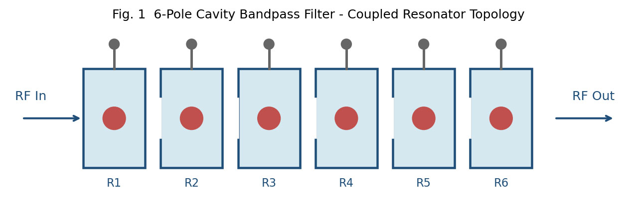
A cavity bandpass filter is implemented as a chain of metallic cavity resonators, each supporting a fundamental TE/TM mode at the target center frequency. Adjacent cavities are coupled inductively or capacitively through irises, tuning screws or probes; the coupling coefficient ki,i+1 defines the passband bandwidth. The input/output ports connect to 50 Ω or 75 Ω transmission lines via tap, loop or probe excitation. A representative six-pole topology is shown in Fig. 1.
2.2 Bandwidth Definitions and Specification Requirements
The following bandwidth definitions are commonly used in 5G cavity BPF design:
- 3 dB Bandwidth (BW3dB): the frequency range over which the transmitted power drops to 50%. The most common design benchmark.
- 1 dB Bandwidth: preferred when low distortion and low EVM are required, e.g. 5G MIMO front-ends.
- Shape Factor = BW1dB / BW60dB: reflects the selectivity; values closer to 1 approach an ideal brick-wall response.
Table 1 summarizes the typical target specification for a Sub-6 GHz macro-cell cavity BPF.
| Parameter | Typical Value | Remarks / Implication |
|---|---|---|
| Center freq. f0 | 3.5 GHz (n78) | Covers 3.3–4.2 GHz n77 / n78 |
| 3 dB Bandwidth | 100 MHz (FBW ≈ 2.86%) | Max single-carrier BW |
| Insertion loss IL | ≤ 0.5 dB | Base-station link budget |
| Return loss S11 | ≤ −15 dB (−20 dB preferred) | In-band reflection |
| Out-of-band rejection | ≥ 50 dB @ f0 ± BW | Adjacent-channel protection |
| Power handling | ≥ 50 W | High-Q metallic cavity |
| PIM | ≤ −153 dBc @ 2 × 43 dBm | Low-PIM construction |
3. Key Design Parameters for Bandwidth Optimization
3.1 Pole Number (N)
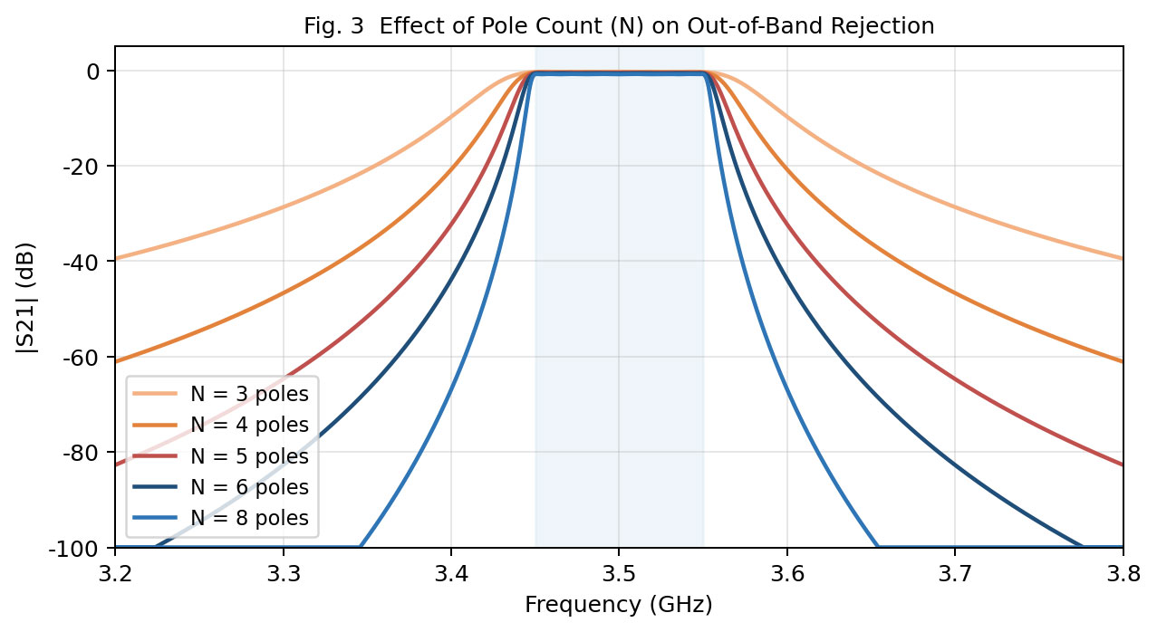
Each additional pole contributes about 20 dB/decade to the out-of-band slope but also raises the in-band IL. For Sub-6 GHz macro-cells, N = 4–6 is the industry-standard balance between selectivity and IL. Fig. 3 shows a Chebyshev approximation (0.05 dB ripple) for several N values.
3.2 Coupling Coefficient (k)
From Cohn's formula, ki,i+1 = FBW / √(gi · gi+1). k directly sets the passband shape and bandwidth: larger k broadens the passband at the cost of increased group-delay ripple, and an excessive k distorts the passband. In practice, iris dimensions are extracted by eigenmode simulation in HFSS / CST.
3.3 Unloaded Cavity Q (Qu)
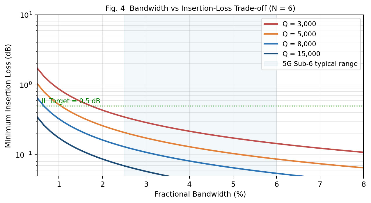
Qu sets the lower bound on in-band IL: ILmin ≈ 4.343 · (f0 / BW3dB) · Σ(gi / Qu) (dB). For fixed Qu, IL is inversely proportional to BW. Typical aluminum cavities reach Qu ≈ 5,000–10,000; silver-plated copper can exceed 30,000. Fig. 4 quantifies this trade-off.
3.4 Transmission Zeros (TZs)
Transmission zeros improve rejection without increasing pole count and are the most effective lever to break the BW–selectivity trade-off. Implementations include: (1) non-adjacent cross-coupling, (2) cul-de-sac topology, (3) multi-mode resonators, and (4) rectangular slots / vias in SIW structures (Nature Sci. Reports, Feb. 2026). Two symmetric TZs typically improve the shape factor by 25–40%.
3.5 S-Parameter Simulation and Passband Performance
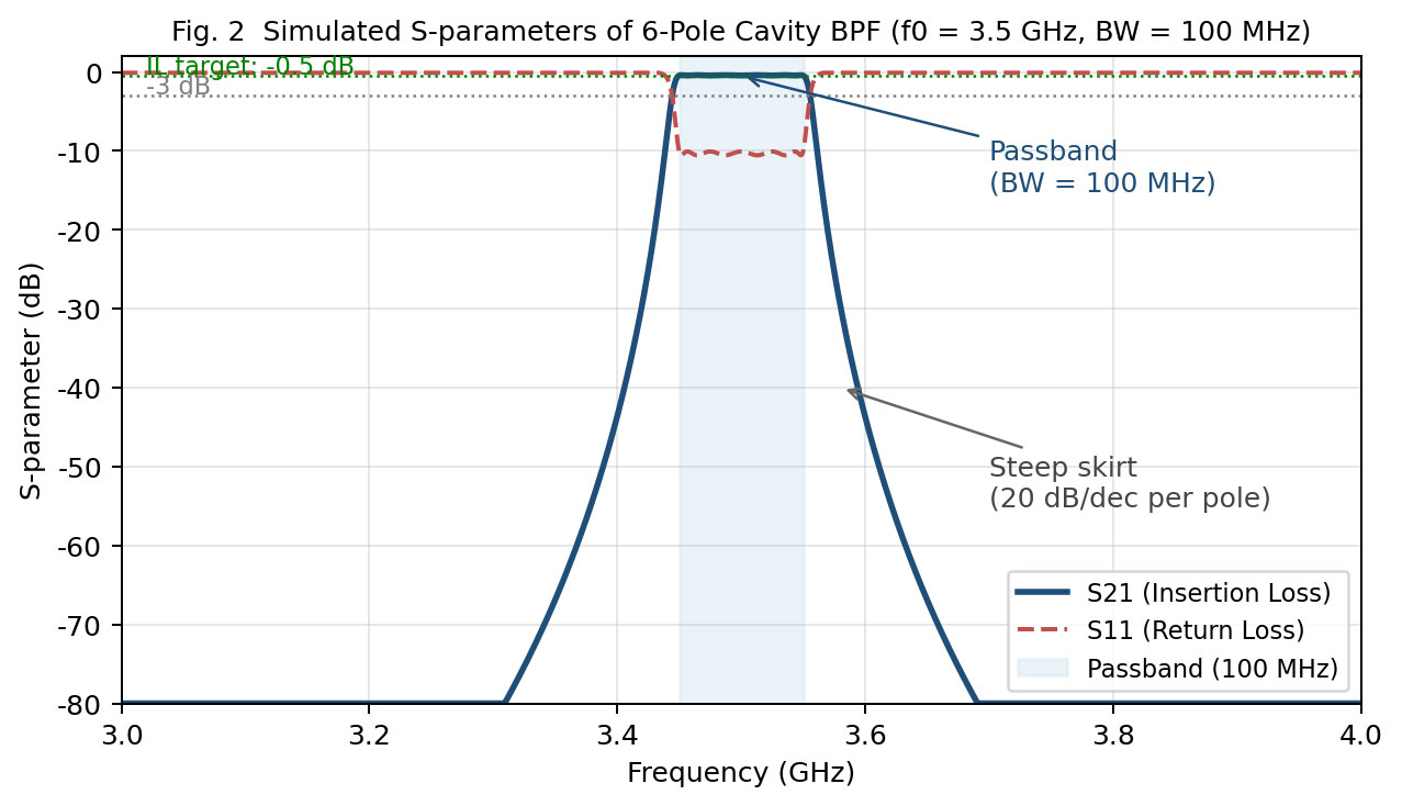
A 6-pole Chebyshev response with symmetric cross-coupled TZs is simulated for f0 = 3.5 GHz, BW = 100 MHz (Fig. 2). At Qu = 8,000 the design yields IL ≈ 0.4–0.5 dB, S11 ≤ −18 dB and rejection ≥ 55 dB at f0 ± 100 MHz — meeting 5G NR n78 macro-cell requirements.
4. Recent Technological Advances (2024 – 2026)
Table 2 summarises the most relevant advances of the past 24 months in bandwidth optimisation of 5G BPFs.
| Source / Year | Technology | Key Data | Implication |
|---|---|---|---|
| PatSnap / IEEE (Apr. 2026) |
SIW – TGSV | Ka-band IL = 0.69 dB/cm | Low-loss mm-wave miniaturization |
| Nature Sci. Reports (Feb. 2026) |
Novel SIW BPF + TZ | Flexible BW + high rejection | Controllable TZs for Sub-6 |
| IJECE V.12 I.7 (Jul. 2025) |
3D-printed honeycomb | IL 3.15 → 1.38 dB (−56%) | Wideband low-loss 3.4–5.5 GHz |
| PIER Letters Vol.116 (2024) |
Microstrip SIR coupled BPF | 9.6 × 8.8 × 1.1 mm³ FBW = 60.2% |
Ultra-wideband n77/n78/n79 |
| Sensors & Materials V.36 N.3 (2024) |
6-cavity SIW mm-wave | f0 = 25.25 GHz FBW = 3.56%, IL = 0.88 dB |
Multi-cavity magnetic coupling |
| TEMWELL (2026 production) |
High-Q Al / Ag-plated cavity | Qu ≈ 8,000; IL ≤ 0.5 dB 7–10-day lead time |
Production-ready Sub-6 GHz |
4.1 AI-Assisted Multi-Objective Optimization
Conventional EM optimisation of ≥6-pole cavity BPFs requires hours of HFSS simulation per iteration. Since 2025–2026, Bayesian optimisation and deep-learning surrogates have been adopted to explore the BW / IL / S11 design space efficiently, reducing design-convergence time by 50–70%. This direction maps to our planned follow-up Article E-50.
5. Design Strategy Matrix
Based on the analysis above, Table 3 presents the design-strategy matrix.
| Scenario | Recommended Topology | Key Parameters | Expected Performance |
|---|---|---|---|
| Wideband Sub-6 BW ≥ 60 MHz |
5–6-pole + symmetric TZs | Larger k, Qu ≥ 8,000 | IL 1.0–2.0 dB Rejection ≥ 55 dB |
| High-power base station IL ≤ 0.5 dB |
4-pole + silver-plated cavity | Qu ≥ 15,000 BW 20–40 MHz |
IL ≤ 0.4 dB |
| Space-constrained | SIW + TZ or multi-layer | Tolerance ±10 μm | IL 1.0–1.5 dB Volume ↓ 70% |
| Multi-band carrier aggregation | Cavity diplexer / multiplexer | Independent BW & isolation |
Isolation ≥ 60 dB PIM ≤ −153 dBc |
6. Conclusions & TEMWELL R&D Capabilities
6.1 Technical Conclusions
- Bandwidth, insertion loss and skirt steepness constitute a fundamental tri-lemma; simultaneous optimization is not possible.
- N = 4–6 remains the mainstream pole count for Sub-6 GHz macro-cells. Production-grade Qu ≈ 8,000 meets BW = 100 MHz, IL ≤ 0.5 dB.
- TZs are the most cost-effective lever, improving the shape factor by 25–40% without adding poles.
- SIW and 3D-printed substrates are strategic for FR2 and miniaturization; metallic cavities remain mainstream for Sub-6.
- AI-assisted optimization is the next differentiation lever — lowering NRE cost and shortening lead time.
6.2 Directly Deployable TEMWELL R&D Capabilities
Leveraging 25+ years of RF filter manufacturing expertise, TEMWELL can translate the above findings directly into product upgrades through five capability pillars:
| R&D Capability | Mapped Technology / Product Line | Deliverable Customer Value |
|---|---|---|
| High-Q cavity design & manufacturing | Cavity BPF series (BP / HP / UWB / LB); Al & Ag-plated options | Qu 8,000–15,000; IL ≤ 0.5 dB |
| TZ & multi-mode design | Custom topologies; 7–10-day lead time | Shape factor improved 25–40% |
| Diplexer / multiplexer integration | TETRA duplexers, LTE low-PIM duplexers, quadriplexers | PIM ≤ −153 dBc @ 2×43 dBm |
| Precision tuning SOP | Automated tuning + measurement SOP | Tuning time ↓ 50% |
| 50/75 Ω dual series + custom | Comm 50 Ω / CATV 75 Ω; full customization | 5G / aerospace / military / UAV / satellite |
6.3 12-Month R&D Roadmap
- Deploy an in-house HFSS + Bayesian-optimization pipeline to shrink 6-pole cavity BPF iteration time from 3 days to 1 day.
- Develop a standard n78 / n79 dual-band low-PIM cavity diplexer aligned with TW & SEA operator spectrum plans.
- Pilot silver-plated Qu > 15,000 premium cavities for high-power and military applications.
- Collaborate with academia to evaluate SIW process introduction for FR2 (24.25–29.5 GHz) miniaturized lines.
- Extend Temstron brand amplifiers / isolators / couplers to deliver turn-key RF sub-system solutions.
TEMWELL, headquartered in Taipei with 25+ years of RF-filter expertise and partners in 20+ countries, offers a full portfolio of cavity, helical, SMD ceramic and SAW filters, plus diplexers / duplexers / multiplexers, and — via the Temstron brand — RF amplifiers and passive components. The optimization strategy proposed here can be mapped directly onto TEMWELL's existing capabilities and delivered within a 7–10-day customization window.
References
- J. Wang, S. Yu, X. Yang, X. Liu, "Bandpass Filter for 5G Sub-6 GHz Bands," Progress In Electromagnetics Research Letters, vol. 116, pp. 79–85, 2024.
- G. R. Asari et al., "A Unified Review of Bandpass Filter Technologies for 5G: Challenges, Trends, and Metamaterial Solutions," SSRG Int. J. Electronics & Communication Engineering, vol. 12, issue 7, pp. 102–118, Jul. 2025.
- J.-M. Huang, H.-T. Xing, Z.-H. Ma, "Substrate-integrated Waveguide Bandpass Filter for 5G Applications," Sensors and Materials, vol. 36, no. 3, pp. 1105–1113, 2024.
- Nature Scientific Reports, "Novel SIW Bandpass Filter with Transmission Zeros for 5G Sub-6 GHz Applications," Feb. 2026.
- PatSnap / IEEE Technical Report, "SIW TGSV Structure Achieving 0.69 dB/cm Insertion Loss at Ka-band," Apr. 2026.
- Fact MR / Future Market Insights, "Global RF Filter Market Forecast 2025–2036," Feb.–Mar. 2026.
- DataInsightsMarket, "5G Cavity Filter Market Analysis – Asia-Pacific Outlook," Apr. 2026.
- 3GPP TS 38.104, "NR; Base Station (BS) Radio Transmission and Reception," Release 17 / 18.
- NDLTD Master Thesis, "Design of a Sub-6 GHz Bandpass Filter with Controllable Transmission Zeros."
- NDLTD Master Thesis, "Design of a 5G Bandpass Filter at 4.2 GHz."
- TEMWELL Corporation, Product Catalog & Technical Datasheets, https://smp.temwell.com, 2026.