

Comparative Study of Matching Networks for 50 Ω and 75 Ω Low Band Cavity Filters
Abstract
Wireless communication systems and cable television (CATV) systems adopted 50 Ω and 75 Ω respectively as their characteristic impedance — a divergence rooted in the physical trade-offs of 1930s coaxial-cable engineering that still shapes the global RF component ecosystem today. Focusing on low band cavity bandpass filters, this paper presents a systematic comparison of the two impedance systems. We first review the historical origins of the 50 Ω and 75 Ω standards; we then quantify the effect of impedance mismatch on transmission efficiency using the reflection coefficient, VSWR and mismatch loss, showing that a direct 50-to-75 Ω connection incurs only about 0.18 dB of mismatch loss. Design procedures for L-type and π-type reactive matching networks and the quarter-wave transformer are derived, and the additional insertion loss of each scheme is compared: reactive matching approaches 0 dB, whereas the resistive minimum-loss pad dissipates 5.7 dB (73% of the incident power). Finally, the specifications of Temwell 50 Ω (ST-WF series) and 75 Ω (7H2L / 7H3L / 5WL2 series) low band cavity filters are cross-referenced, leading to a practical guideline: selecting a filter in the system's native impedance eliminates the cross-impedance overhead at the source and is the most economical way to minimize overall insertion loss.
1. Introduction: Historical Background of the 50 Ω and 75 Ω Standards
1.1 Origin of the 50 Ω Standard — a Power/Loss Compromise
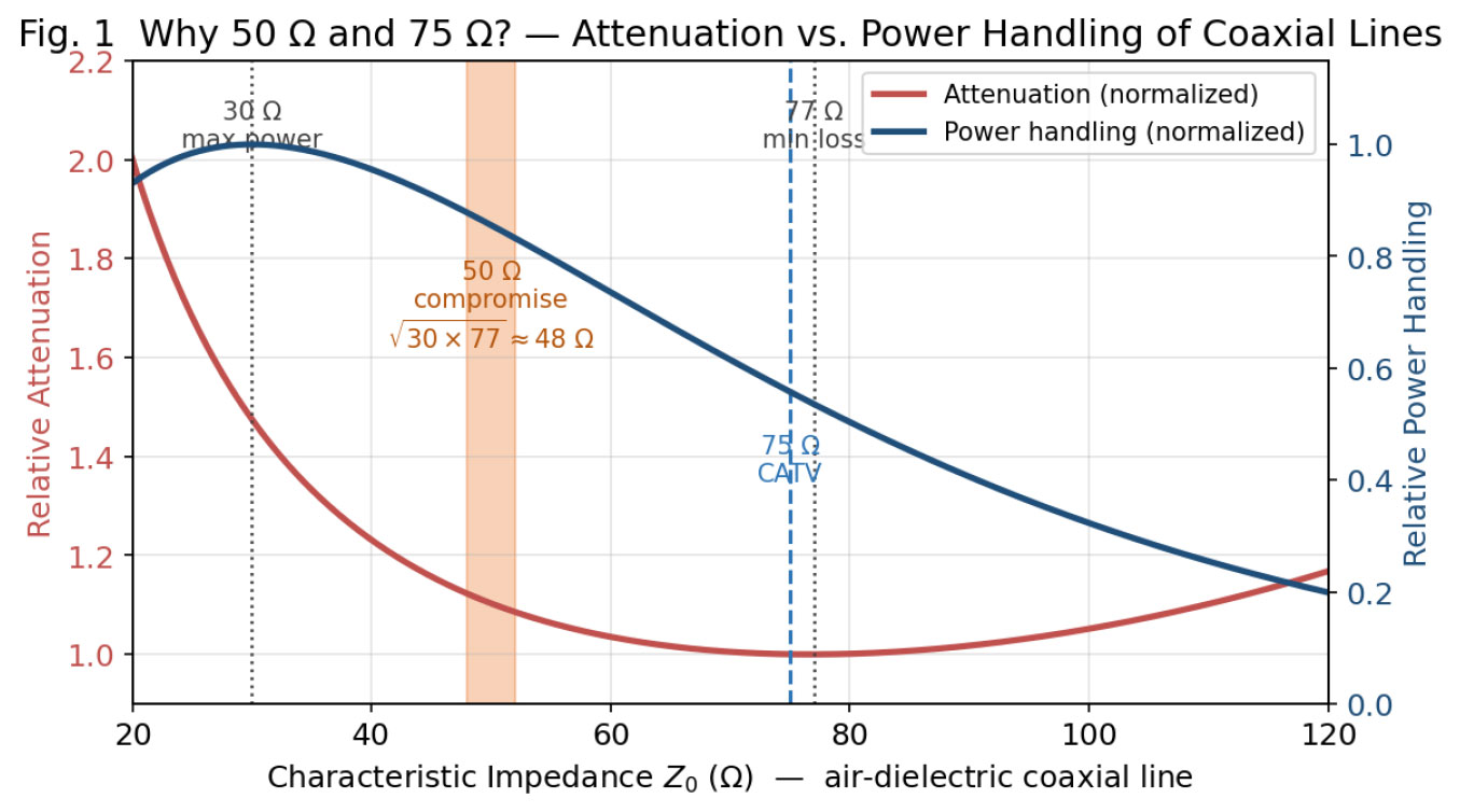
The 50 Ω standard traces back to the 1930s, when air-dielectric coaxial cables were developed for kilowatt-class radio transmitters. For an air-line coax there are two key physical optima: breakdown power handling peaks at about 30 Ω (conductor-diameter ratio ≈ 1.65:1), while attenuation reaches its minimum near 77 Ω (ratio ≈ 3.6:1). Engineers took the geometric mean √(30 × 77) ≈ 48 Ω and rounded it to 50 Ω as the compromise between power handling and low loss (Fig. 1) [1][2]. In 1949 the U.S. military codified both 50 Ω and 75 Ω grades in MIL-C-17; AT&T/Bell Labs' long-haul microwave networks and HP (now Keysight) instrumentation subsequently standardized on 50 Ω, cementing it as the de-facto standard for wireless communications, radar, avionics and test & measurement [2][3].
1.2 Origin of the 75 Ω Standard — Low Loss and the Antenna Connection
Several engineering considerations converged on 75 Ω. The attenuation minimum of an air-dielectric coax sits near 77 Ω, of which 75 Ω is a practical approximation; commercial CATV cables, however, use foamed polyethylene dielectric (εr ≈ 1.4–1.5), shifting the true minimum-loss impedance to roughly 64 Ω [1][3]. A more compelling historical explanation comes from antenna systems: a 300 Ω folded dipole fed through the classic 4:1 balun yields exactly 75 Ω, making it the natural interface for broadcast and TV receiving systems. CATV signals carry very little power, so low attenuation over long runs dominates; the thinner center conductor of 75 Ω cable also makes it lighter and more flexible for residential wiring [1][4]. Today 50 Ω dominates wireless/test while 75 Ω dominates CATV, satellite TV and video distribution — two parallel ecosystems.
2. Impedance System Differences: Effect on Transmission Efficiency
2.1 Reflection Coefficient and VSWR
When a signal travelling on a line of characteristic impedance Z0 meets a load ZL, the voltage reflection coefficient is Γ = (ZL − Z0)/(ZL + Z0). For a 50 Ω system driving a 75 Ω load, Γ = (75 − 50)/(75 + 50) = 0.2, corresponding to VSWR = 1.5:1 and a return loss RL = −20 log10(0.2) ≈ 13.98 dB.
2.2 Quantifying Mismatch Loss
The power lost to reflection is the mismatch loss, ML (dB) = −10 log10(1 − |Γ|²). For the 50-to-75 Ω case, ML ≈ 0.18 dB — only about 4% of the incident power is reflected while 96% is delivered forward (Fig. 2) [5][6]. This is benign for most applications, with two caveats: reflections introduce a measurement uncertainty of roughly ±0.35 dB peak-to-peak, which matters in precision metrology [7]; and an unintended termination impedance alters the loaded Q at the filter ports, detuning its center frequency and bandwidth and corrupting IMD and desensitization measurements [7]. Table 1 lists the mismatch loss for common VSWR values.
| VSWR | Reflection Coeff. Γ | Return Loss (dB) | Mismatch Loss (dB) | Reflected Power (%) |
|---|---|---|---|---|
| 1.0:1 | 0 | ∞ | 0 | 0% |
| 1.2:1 | 0.091 | 20.8 | 0.036 | 0.8% |
| 1.5:1 (50↔75 Ω) | 0.200 | 13.98 | 0.177 | 4% |
| 2.0:1 | 0.333 | 9.54 | 0.512 | 11% |
| 3.0:1 | 0.500 | 6.02 | 1.249 | 25% |
2.3 Mismatch Loss vs. Insertion Loss
Mismatch loss is only one component of insertion loss. Total IL comprises the reflective mismatch loss plus dissipative loss (conductor and dielectric losses converted to heat). Cavity filters, built on high-Q resonators, exhibit far lower dissipative loss than planar circuits, but the dissipation of any added matching network must still be accounted for [5].
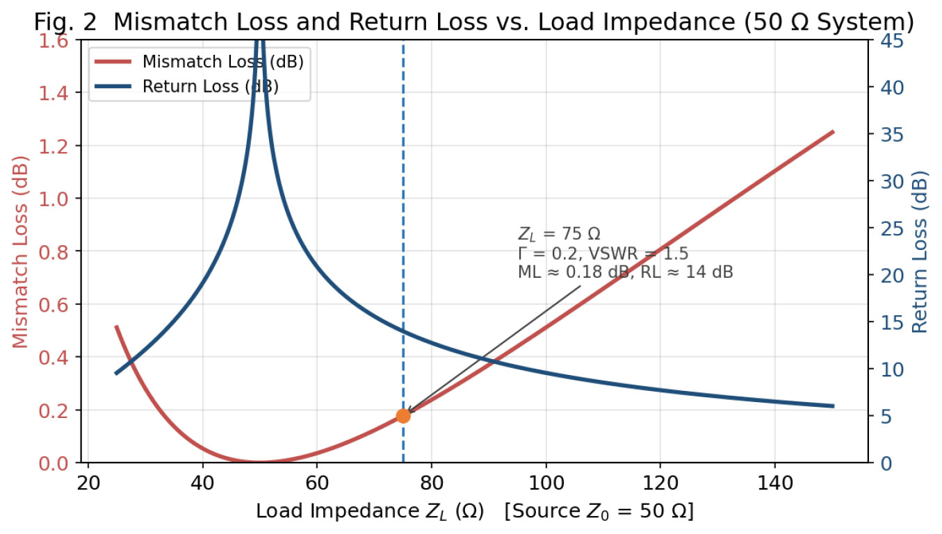 Fig. 2 Mismatch loss and return loss vs. load impedance in a 50 Ω system. At ZL = 75 Ω: Γ = 0.2, VSWR = 1.5, ML ≈ 0.18 dB, RL ≈ 14 dB.
3. Matching Network Design: 50↔75 Ω Conversion Principles
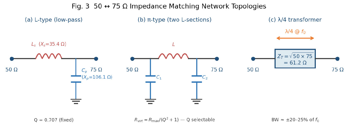
When 50 Ω and 75 Ω systems must be interconnected, a matching network removes the impedance discontinuity. The usual topologies are the lumped L-type and π-type networks, the distributed quarter-wave transformer, and the broadband but lossy resistive pad (Fig. 3).
3.1 L-Type Matching Network
The L-network is the minimal two-element circuit: a series reactance Xs and a shunt reactance Xp. Its Q is fixed by the impedance ratio: Q = √(RP/RS − 1) = √(75/50 − 1) ≈ 0.707, giving |Xs| = Q·RS = 35.4 Ω (series element, 50 Ω side) and |Xp| = RP/Q = 106.1 Ω (shunt element, 75 Ω side) [8][9]. The two elements must be of opposite type (one inductive, one capacitive), yielding low-pass (series L + shunt C) or high-pass (series C + shunt L) forms. With its fixed low Q (0.707) the match is relatively wideband — ideal for single-band low-loss conversion, with a measured excess loss of only ≈ 0.05 dB [10].
3.2 π-Type Matching Network
The π-network is two back-to-back L-sections sharing a virtual resistance Rvirt = Rmax/(Q² + 1), where Rmax is the larger termination and Q is chosen by the designer (Rvirt must be smaller than both terminations) [11][12]. Its key advantage is a selectable Q: higher Q narrows the matching bandwidth and improves out-of-band harmonic rejection — useful when impedance conversion and extra selectivity are wanted simultaneously; capacitive topologies also provide DC blocking. The price is more components and a more complex alignment [12].
3.3 Quarter-Wave Transmission-Line Transformer
In distributed designs the quarter-wave transformer is the most elegant solution: a line of characteristic impedance ZT = √(50 × 75) ≈ 61.2 Ω and electrical length λ/4 at the operating frequency completes the match [13][14]. Its inherent selectivity limits the matching bandwidth to about ±20–25% of f0. A related trick is the twelfth-wave transformer — splices of standard 50 Ω and 75 Ω cable, each about λ/12 long — achieving ≈ 0.05 dB excess loss with no special-impedance line at all [15].
3.4 Resistive Minimum-Loss Pad
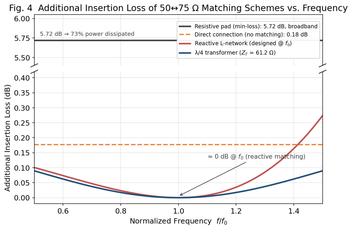
A minimum-loss pad of a 43.3 Ω series and an 86.6 Ω shunt resistor provides a frequency-independent broadband match and is standard practice in instrument calibration; however its insertion loss is 5.7 dB — 73% of the power is dissipated as heat [10][16]. It should never be placed in an operational signal chain. Fig. 4 compares the additional insertion loss of all matching schemes versus frequency.
4. Insertion Loss Comparison of Low Band Cavity Filters
4.1 Theoretical Lower Bound of Cavity Filter IL
The passband IL of a cavity BPF relates to the unloaded resonator Q as IL (dB) ≈ 4.343·Σgi / (Qu · FBW), where gi are the low-pass prototype values and FBW is the fractional bandwidth [17]. Three rules follow: narrower bandwidth means higher loss; higher Qu means lower loss (cavity resonators achieve Qu = 5,000–20,000, far above the 200–1,000 of helical filters); and higher order raises Σgi and hence loss. The impedance system itself does not change Qu — IL differences arise from port matching design and cross-impedance overhead.
4.2 Typical IL of 50 Ω Standard Low Band Cavity Filters
The Temwell ST-WF series is designed for 50 Ω systems and spans 435 MHz to 2.9 GHz with IL between 0.5 and 2.0 dB; VSWR is specified at 1.3:1 (≈ 17.7 dB return loss) across the series (Table 2, Fig. 5) [18]. The inverse IL–FBW relationship is clearly visible: the ST-WF11-2900S with FBW = 13.9% needs only 0.5 dB, while narrowband models at FBW = 1.7–2.2% require 1.0 dB or more.
| Part No. | Center Freq. (MHz) | Passband (MHz) | BW (MHz) | IL (dB) | VSWR | Power (W) |
|---|---|---|---|---|---|---|
| ST-WF01-435S | 435 | 425–445 | 20 | 2.0 | 1.3:1 | 20 |
| ST-WF03-632N | 632 | 625–639 | 14 | 1.0 | 1.3:1 | 100 |
| ST-WF04-707N | 707 | 697–717 | 20 | 1.0 | 1.3:1 | 100 |
| ST-WF05-881S | 881 | 869–894 | 30 | 1.5 | 1.3:1 | 25 |
| ST-WF06-942S | 942 | 925–960 | 35 | 1.5 | 1.3:1 | 25 |
| ST-WF07-1200S | 1200 | 1190–1210 | 20 | 1.0 | 1.3:1 | 10 |
| ST-WF10-2425S | 2425 | 2400–2450 | 50 | 1.5 | 1.3:1 | 25 |
| ST-WF11-2900S | 2900 | 2698–3102 | 404 | 0.5 | 1.3:1 | 5 |
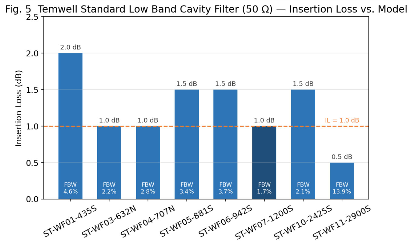 Fig. 5 Insertion loss and FBW across the Temwell ST-WF series (50 Ω). The wideband ST-WF11 (FBW 13.9%) achieves 0.5 dB, confirming the inverse IL–FBW relationship.
4.3 IL Considerations in 75 Ω Systems
75 Ω cavity and helical filters are optimized for CATV bands. In the Temwell 7H2L series, the TDL6262F-735.25M (Fc = 735.25 MHz, 6 MHz narrowband design) shows a typical IL of about 5 dB with return loss ≥ 12 dB [19]; the Mini-Circuits ZFBP-1100-75+ (950–1250 MHz) achieves a typical IL of just 0.8 dB at VSWR 1.27:1 [20]. IL levels of 75 Ω products are thus on par with 50 Ω counterparts — differences are governed by FBW and filter order, not by the impedance itself.
4.4 Total Loss Stack-Up in Cross-Impedance Systems
When a 50 Ω source drives a 75 Ω cavity filter (or vice versa), total system IL is the sum of: (1) the filter's own IL; (2) ≈ 0.18 dB mismatch loss if directly connected; (3) the matching network's own loss — near 0 dB reactive, up to 5.7 dB resistive. Moreover, a non-design termination shifts the filter's effective loaded Q, distorting the passband and detuning the resonance — often more critical than the 0.18 dB power penalty. Full-wave verification in ADS/HFSS is recommended [7][17].
5. Temwell Product Portfolio: 50 Ω vs. 75 Ω Low Band Cavity Filters
Temwell is a specialist manufacturer offering low band cavity filters in both 50 Ω and 75 Ω, covering DC to 60 GHz. The 50 Ω lines (7H2, 7H3 and the ST-WF standard cavity series) target wireless communications and test equipment, while the 'L'-suffixed series (7H2L, 7H3L, 5WL2) are dedicated 75 Ω designs for CATV and video distribution (Table 3). All series support N, SMA and SMD connectors, power handling up to 200 W, out-of-band rejection beyond 60 dB, and IP66/IP67 waterproof and Low-PIM options [18][21][22].
| Series | Impedance | Center Freq. Range | BW Range | Primary Applications |
|---|---|---|---|---|
| ST-WF (Standard Low Band Cavity) | 50 Ω | 400 MHz – 3 GHz | 14 – 404 MHz | Wireless comms, radar, base stations, test |
| 7H2L Series | 75 Ω | 42 – 1500 MHz | 5 – 120 MHz | CATV, broadcast TV |
| 7H3L Series | 75 Ω | 42 – 1500 MHz | 5 – 120 MHz | CATV, high-rejection applications |
| 7S Series | 50/75 Ω | 196 – 1500 MHz | 5 – 120 MHz | General wireless & cable TV |
| 5WL2 Series | 75 Ω | 230 – 2600 MHz | 2 – 120 MHz | Wideband CATV |
| 5R Series | 50/75 Ω | 200 – 2600 MHz | 5 – 120 MHz | High-frequency comms & test |
The 50 Ω cavity filters are engineered for wireless power scenarios — N-connector models handle 100 W or more — whereas the 75 Ω series serve low-power CATV distribution (typically 1–5 W). The VSWR ≤ 1.3:1 of the Temwell standard cavity series represents excellent matching within the design impedance system; crossing impedance requires an external matching circuit to reach the same level [18][19].
6. Selection Guidelines: Choosing the Right Product
6.1 Selection Decision Flow
- Confirm the system impedance: identify the native impedance (50 Ω or 75 Ω) of source, lines and load — the native impedance governs.
- Avoid cross-impedance design: prefer a filter matching the system impedance to eliminate mismatch loss and matching overhead at the source.
- If crossing impedance is unavoidable: use low-loss reactive matching (L / π) or a λ/4 (λ/12) transformer; never place a resistive pad in a power path.
- Check return loss: target > 20 dB (VSWR ≈ 1.22:1, < 1% reflected power) in-band; maintain at least 15–20 dB.
6.2 Application Scenario Mapping
| Application | Impedance | Temwell Series | Notes |
|---|---|---|---|
| 5G base station (Sub-6 GHz) | 50 Ω | ST-WF04-707N, ST-WF05-881S | Check connector type (N/SMA) |
| TETRA / DMR professional radio | 50 Ω | ST-WF01-435S | Mind power handling |
| Aeronautical comms (L-band) | 50 Ω | ST-WF07-1200S | Tight temperature stability |
| CATV signal distribution | 75 Ω | 7H2L / 7H3L Series | Low loss first; IL < 2 dB |
| DOCSIS 3.1 / MoCA | 75 Ω | 5WL2 Series | Wideband design required |
| 50 Ω equipment testing a 75 Ω DUT | Cross-impedance | Any series + matching network | Prefer VNA + de-embedding |
| Radar systems | 50 Ω | ST-WF04/07 (high-power) | Power handling is critical |
6.3 Matching Scheme Comparison
| Matching Scheme | Extra IL | Bandwidth | Complexity | Recommended Use |
|---|---|---|---|---|
| Reactive L-network | ≈ 0.05 dB | Moderate (Q = 0.707) | Low | Single-band low-loss conversion |
| Reactive π-network | ≈ 0 dB | Narrow (Q selectable) | Medium | Where extra rejection is wanted |
| λ/4 transformer | ≈ 0 dB | ±20–25% BW | Low | PCB / coaxial distributed systems |
| λ/12 coaxial transformer | ≈ 0.05 dB | Specific band | Low | Amateur / broadcast receive |
| Resistive pad | ≈ 5.7 dB | Broadband (from DC) | Lowest | Test & calibration only |
| Direct connection (unmatched) | ≈ 0.18 dB | All frequencies | None | Non-critical, loss-tolerant links |
7. Conclusions: The System-Level Impact of Impedance Matching
- Both impedance standards rest on solid physics — 50 Ω is the geometric-mean compromise between the power-handling optimum (30 Ω) and the minimum-attenuation point (77 Ω); 75 Ω follows naturally from low-loss transmission and the 4:1 balun transformation of the folded dipole [1][2].
- A direct 50-to-75 Ω connection loses only ≈ 0.18 dB (4% reflected power) — far less than intuition suggests; its second-order effects on filter detuning and measurement uncertainty must nevertheless be respected in precision systems [5][7].
- Reactive networks and the λ/4 transformer achieve near-zero-loss conversion and are the preferred interconnect; the resistive pad dissipates 5.7 dB (73% of power) and belongs only in instrument calibration [10][16].
- Cavity filter IL is set by Qu, FBW and filter order; the impedance system itself does not alter Qu. Temwell ST-WF data confirm IL ∝ 1/(Qu·FBW) [17][18].
- Correct product selection is the most economical fix — Temwell offers both 50 Ω (ST-WF, 7H2, 7H3) and 75 Ω (7H2L, 7H3L, 5WL2) standard lines; select the native-impedance model directly, and use VNA + S-parameter de-embedding for cross-system test [18][23].
Impedance matching is the foundation of signal integrity and system stability. In either a 50 Ω or a 75 Ω system, keeping the low band cavity filter consistent with the source and load impedance maximizes power transfer, minimizes standing waves and reflections, and is the most effective route to lower system insertion loss and higher overall transmission efficiency.
References
[1] Microwaves101, "Why Fifty Ohms?," microwaves101.com.
[2] Vik's Newsletter, "Why 50 Ohms Became the RF Standard," viksnewsletter.com.
[3] B. Schweber, "Selecting the Right Transmission Line Impedance — The Reasons for 50 Ω and 75 Ω Transmission Lines," DigiKey Article Library, Apr. 2022.
[4] MW101, "Coaxial Cable Impedance Explained: 50 Ω vs 75 Ω," technical note.
[5] rfessentials.com, "How to Calculate Mismatch Loss in dB from Known VSWR," RF Knowledge Base.
[6] 3roam.com, "Impedance Mismatch Loss Calculator (with Examples)."
[7] F. Goh and J. Kelly, "Effects of Noise Floor, Linearity & Mismatch Error on RF Measurements," Verigy Technical Article.
[8] M. Steer, Microwave and RF Design III — Networks, Ch. 6.4 "The L Matching Network," LibreTexts Engineering.
[9] High Frequency Electronics, "Design Notes: L-Network Impedance Matching," Apr. 2010.
[10] Orbit6, "50 Ohm Impedance Matching Calculator — Resistive and Reactive 50↔75 Ω Networks."
[11] University of Utah ECE 5321, Lecture 16: "Matching Networks — Pi and T Topologies."
[12] Silicon Labs, AN1275: "Impedance Matching Network Architectures."
[13] VK1KRF, "Quarter Wave Coaxial Transformer: Matching 50 to 75 Ohm Coaxial Cable."
[14] W8JI, "75 Ohm to 50 Ohm Transmission Line Transformers — How It Works."
[15] W4SAT, "Quarter Wave & Twelfth-Wave Line Matching Transformers."
[16] rfcafe.com, "Minimum Loss Matching Pad (50 Ω ↔ 75 Ω): 5.72 dB Insertion Loss."
[17] rfessentials.com, "Filter Bandwidth, Insertion Loss, and Q Factor," RF Knowledge Base.
[18] Temwell Corporation, "Standard Low Band Cavity Filter — Technical Datasheets (ST-WF Series)," temwell.com.
[19] Temwell Corporation, "Bandpass Filter TDL6262F-735.25M (7H2L Series, 75 Ω)," product datasheet.
[20] Mini-Circuits, "ZFBP-1100-75+ 75 Ω Cavity Bandpass Filter," datasheet.
[21] Temwell Group, "Cavity Filter Product Overview — Impedance: 50 ohm, 75 ohm; IP66/IP67; Low PIM," Mar. 2022.
[22] Temwell Corporation, "5G Cavity Filter — Custom Design Capability, DC to 60 GHz," product category page.
[23] Temwell Corporation, "5G Helical Bandpass Filter — Center Frequency 42–1500 MHz, Impedance 50 & 75 ohm," product category page.